ISSN ONLINE(2278-8875) PRINT (2320-3765)
ISSN ONLINE(2278-8875) PRINT (2320-3765)
V.Vengatesan1, M.Chindamani2
|
| Related article at Pubmed, Scholar Google |
Visit for more related articles at International Journal of Advanced Research in Electrical, Electronics and Instrumentation Engineering
For electrical drives good dynamic performance is mandatory so as to respond to the changes in command speed and torque. This requirement of AC drives can be fulfilled by the vector control method which enables the control of field and torque of induction motor independently (decoupling) by manipulating corresponding field oriented quantities. The traditional indirect vector control system uses conventional PI controller in the outer speed loop because of the ease and constancy, unexpected change in load conditions or environmental factors produce overshoot, fluctuation of motor speed, oscillation of the torque and long settling time causes deterioration of drive performance. An intelligent controller based on Fuzzy Logic can be used in the place of PI regulator to overcome. In this paper application of fuzzy logic to the intelligent SVPWM based speed control of induction motor drive is investigated. To solve the objective of this paper MATLAB/ SIMULINK software is used. The superior control performance of the proposed controller is demonstrated at SIMULINK platform using the fuzzy logic tool box.
Keywords |
| Fuzzy logic control, Indirect Field Oriented Control, Space Vector Pulse Width Modulation, Induction motor. |
INTRODUCTION |
| In recent years, the field oriented control of induction motor drive is widely used in high performance drive system, because of its advantages like high efficiency, very simple, extremely rugged, good power factor. Induction motor is used in many applications such as Industrial drives, automotive control, etc. In the modern years there has been a great demand in industry for adjustable speed drives. |
| The Space Vector Pulse Width Modulation (SVPWM) method is an advanced, computation-intensive PWM method and best among all the PWM techniques. Because of its superior performance characteristics, it has been finding wellknown application in recent years. The Pulse Width Modulation methods discussed so far have only considered implementation on half bridges operated independently, giving suitable Pulse Width Modulation methods performance. With a machine load, the load neutral is normally isolated, which causes interface among the phases. This interface was not considered before in the Pulse Width Modulation discussion. |
| Recently, Fuzzy logic control has found many applications in the past decade. FLC has proven effective for complex, non-linear and inaccurately defined processes for which standard model based control techniques are impractical or impossible. Fuzzy controller deals with problems that have imprecision, ambiguity and use membership functions with values varying between 0 and 1. This means that if the reliable practiced knowledge is not available or if the controlled system is too difficult to derive the required decision rules, development of a FLC become time consuming and sometimes impossible. In the case that the practiced knowledge is available, fine-tuning of the controller might be time consuming as well. Furthermore, an optimal FLC cannot be achieved by trial-and-error. These drawbacks have limited the application of fuzzy logic control. Some difficult tasks have been made to solve these problems and simplify the task of tuning parameters and developing rules for the controller. These approaches mainly use adaptation or learning techniques drawn from artificial intelligence or neural network theories. |
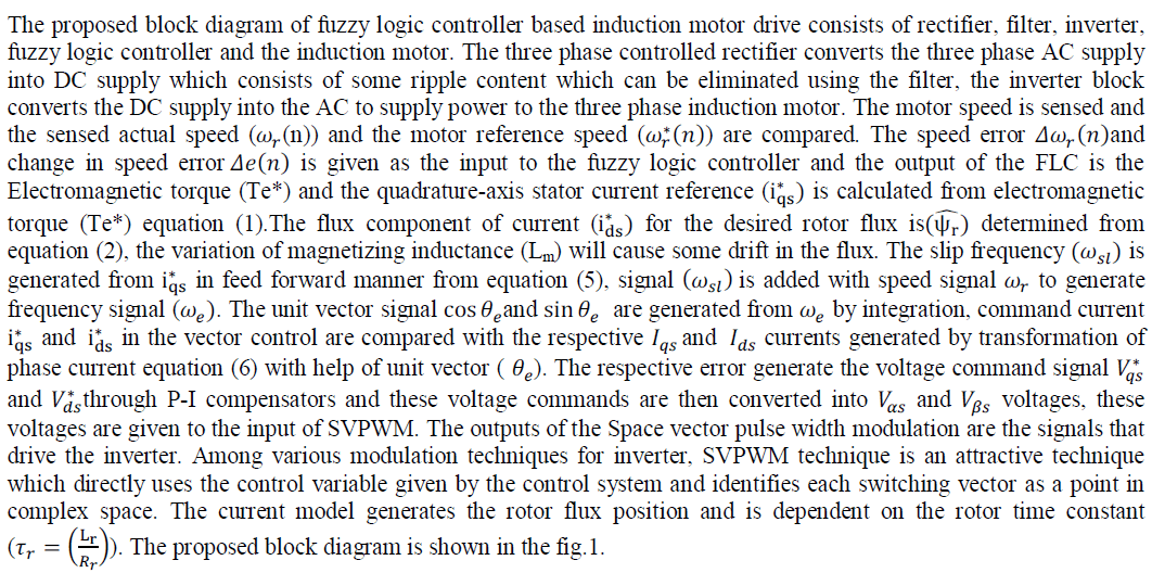
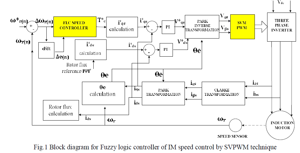
II. BLOCK DIAGRAM OF SPEED CONTROL OF THREE PHASE INDUCTION MOTOR USING FUZZY LOGIC CONTROLLER BY SPACE VECTOR MODULATION TECHNIQUE |
 |
 |
A. PRINCIPLE OF FIELD-ORIENTED CONTROL: |
| The construction of a DC machine is such that the field flux and armature flux are perpendicular to each other. Being orthogonal, these two fluxes produce no net interaction on one another. Adjusting the field current we can control the DC machine flux, and by adjusting armature current torque can be controlled independently. Because of interactions between the stator and rotor fields an AC machine is not so simple in which orientations are not held at 90 degrees. DC machine-like performance can be obtain in holding a fixed and orthogonal orientation between the field and armature fields in an AC machine. To attain independently controlled flux and torque by orientation of the stator current with respect to the rotor flux, such a control scheme is called flux-oriented control or vector control and it is applicable to both induction and synchronous motors. |
| 1. The induction motor is fed by a voltage source SVPWM inverter. The motor speed ω is compared with the reference speed ω* and the error is produced which is fed to the speed controller. The output of speed controller is electromagnetic torque Te*. |
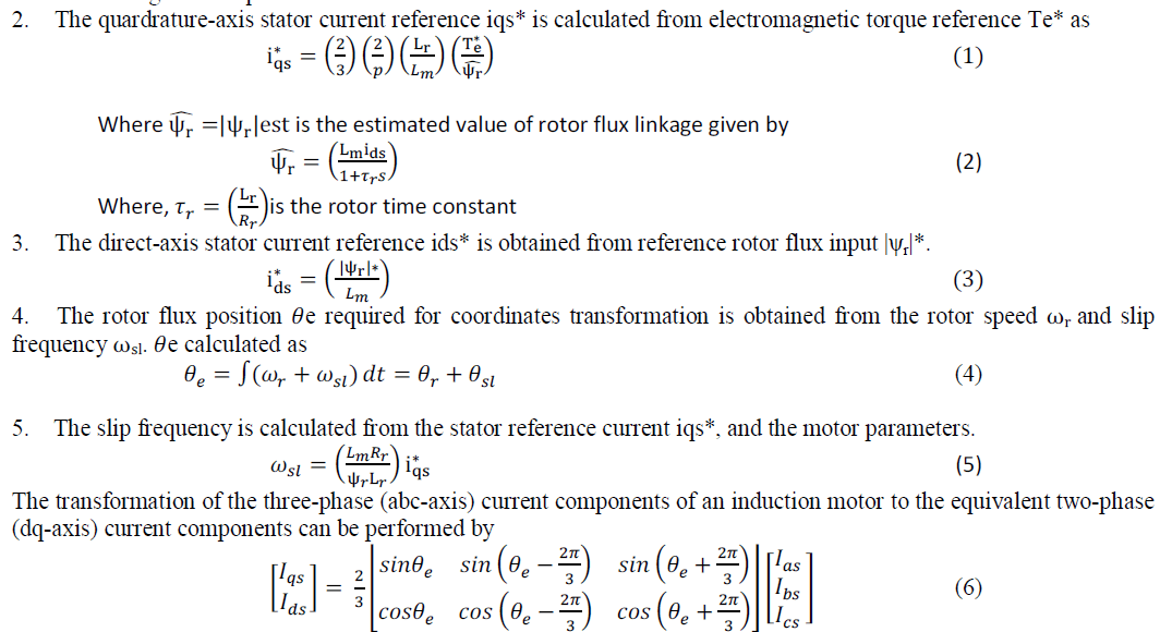 |
| The three-phase current components ias, ibs, and ics are in stationary reference frame which does not rotate in space whereas the two phase current components ids, iqs are in the synchronous reference frame whose direct and quadrature axes rotate in space at the synchronous speed. |
B.PRINCIPLE OF SPACE VECTOR MODULATION: |
| The concept of space vectors is derived from modulating the inverter output voltage from the rotating field of AC. In this technique the three phase quantities can be transformed to their equivalent 2-phase quantity either in synchronously rotating frame or stationary frame. From this 2-phase component the reference vector magnitude can be found and used for modulating the inverter output. By using active and zero space vectors the active and zero switching states can be determined. The space vector diagram for the three-level inverter is shown in the Fig.2 where the six active vectors V1 to V6 form a regular hexagon with six equal sectors (I to VI). The zero vector V0 lies on the center of the hexagon. From this analysis, the space vector modulation task can be solved into following steps to make the actual PWM pattern. |
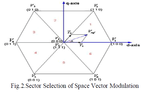 |
| Step 1: Sector Identification: By comparing the stationary frame d-q components of the reference voltage vector, the sector where the reference vector is located is identified. |
| Step 2: Calculating the Effective Timer: Using the d-q components of reference vector and the DC link voltage information, the effective times T1, T2 are calculated. |
| Step 3: Determining the switching Times: using the corresponding sector information the actual switching time for each inverter leg is generated from the combination of the effective times and zero sequence time. |
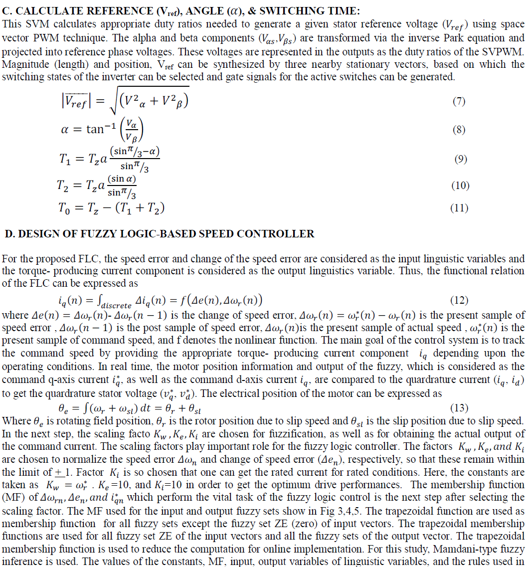
C. CALCULATE REFERENCE (Vref), ANGLE (ïÿýïÿý), & SWITCHING TIME: |
 |
| this study are selected by trial and error to obtain the optimum drive performances. In this study, the center of gravity defuzzificaion is used. Each of the inputs and the output contain membership functions with all these four fuzzy sets. |
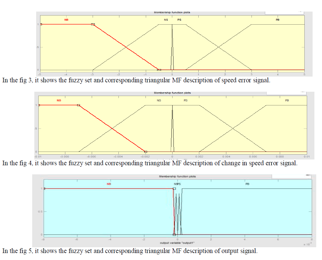 |
| The fuzzy sets are defined as follows: PS=Positive Small PB: Positive Big NS= Negative Small NB= Negative Big |
| The universe of discourse of all the variables, covering the whole region, is expressed in per unit values. All the MFs are asymmetrical because near the origin (steady state), the signals require more precision. There are four MFs for error and change of error signals, where as there are four MFs for output. All the MFs are symmetrical for positive and negative values of the variables.The mapping of the fuzzy inputs into the required output is derived with the help of a rule base as given in table.1. |
 |
III. SIMULATION RESULTS |
| The simulation details of the three phase induction motor is explained .In this the proposed method SVPWM speed control strategy for induction motor drives is explained. The simulation of speed control of induction motor was done using the software package MATLAB/SIMULINK. For this purpose, the motor’s block diagram, space vector modulation blocks are constructed using closed loop models .After running the closed loop model motor speed was analyzed. |
A.OUTPUT CURRENT AND TORQUE CHARACTRISTIC: |
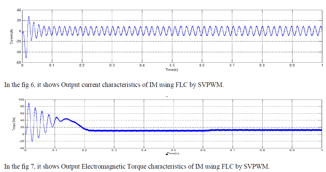
| The output current and torque response of IM drive using SVPWM technique is shown in the fig.6, fig.7. |
 |
B.OUTPUT SPEED CHARACTRISTIC: |
| The output speed response of IM drive using FLC by SVPWM technique is shown in the fig.9. & without FLC is shown in fig.8. In this paper rise time is less also the actual speed can be settled as fast as possible by using fuzzy logic controller. |
 |
| In the fig 9, it shows Output speed characteristics of IM using SVPWM, the actual speed is settled at 0.8s and the rise time is high. |
 |
| In the fig 9, it shows Output speed characteristics of IM using FLC with SVPWM technique, the actual speed is settled at 0.3s and the rise time is very less. |
CONCLUSION |
| Fuzzy logic controller based speed control of Induction Motor drive has been simulated using MATLAB. The simulated results show the improved performance of speed control of the Induction Motor by a SVPWM voltagesource inverter (VSI). The simulation results also show that the speed response of fuzzy controller with improved performance compare to SVPWM and conventional controller. |
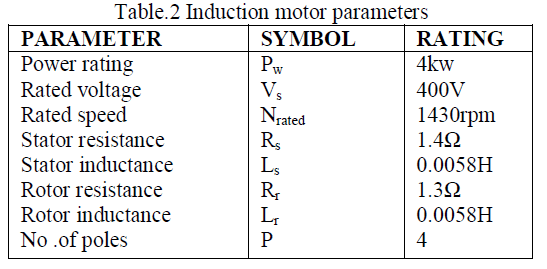
| The parameters of the motor used for the simulation in MATLAB are shown in table 2. |
 |
References |
|