ISSN ONLINE(2319-8753)PRINT(2347-6710)
ISSN ONLINE(2319-8753)PRINT(2347-6710)
Anil Wadhokar 1, Krupanshu Sakharikar 2, Sunil Wadhokar 3, Geeta Salunke 4
|
| Related article at Pubmed, Scholar Google |
Visit for more related articles at International Journal of Innovative Research in Science, Engineering and Technology
Now days there are different methods are present for evaluation of features of images, but there is no common effort developed for the comparison of the quality of image. We, in this paper are interested in quality evaluation of images so we are capturing the images from different cameras. The cameras we are using are of different configurations, specification and companies. The first work here is to capture the same scene with different cameras. While capturing the image, image can be affect by different types of distortion which we are discussing in this paper. The next step is to extract the special features of images. There are several features on the basis of which we can compare the quality of images. These features are contrast, luminance, edge base structure index, structural similarity(SSIM) etc. For advancement as we are extracting features of image and for quality improvement we are processing image with techniques for better result. Hence we can get the best quality image on the basis of comparison.
Keywords |
| Camera quality, comparison functions, quality, special features, indices, ssim. |
INTRODUCTION |
| As electronics is growing field so day by day there is improvement in quality of image. Camera configurations are getting improved. Previously we use a VGA that is video graphics accessories camera but now a day due to advancement in imaging field we are able to use HD that is high definition cameras. Talking about image quality evaluation, it is based on two types first is subjective quality evaluation and second is objective quality evaluation. Subjective measurements are the result of human observers providing their opinion of the video quality. Objective measurements are performed with the aid of instrumentation, calibrated scales and mathematical algorithms. There are lots of cameras applications for capturing images, making video, video conferencing, use in news studio, film studios etc. Now a day’s 3D cameras are available to capture 3D images. The concept behind 3D image is creating the depth which is done by 2-D slightly different scenes on the retina of each eye. The human brain creates the impression of depth through physiological fusing of the stereoscopic pair. In this paper we firsrt capture the images from cameras. The captured images are then photo-metrically and geometrically calibrated before being displayed. Different views captured by different cameras may vary in terms of colour, brightness, noise level, and orientation. |
RELATED WORK |
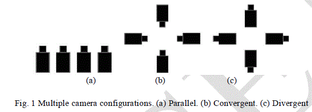
| Digital images are subject to a wide variety of distortions during acquisition, processing, compression, storage, transmission and reproduction, any of which may result in a degradation of visual quality. For applications in which images are ultimately to be viewed by human beings, the only “correct” method of quantifying visual image quality is through subjective evaluation. In practice, however, subjective evaluation is usually too inconvenient, timeconsuming and expensive. The goal of research in objective image quality assessment is to develop quantitative measures that can automatically predict perceived image quality. An objective image quality metric can play a variety of roles in image processing applications. First, it can be used to dynamically monitor and adjust image quality. For example, a network digital video server can examine the quality of video being Transmitted in order to control and allocate streaming resources. Second, it can be used to optimize algorithms and parameter settings of image processing systems. For instance, in a visual communication system, a quality metric can assist in the optimal design of pre-filtering and bit assignment algorithms at the encoder and of optimal reconstruction, error concealment and post filtering algorithms at the decoder. Many companies now a day’s working for objective quality metrics for single view images, videos. The work dedicated for objective multiple view image quality assessment is not much as needed now, on the other hand, is much less. Leorin had used subjective tests to show that current single video camera quality assessment techniques are not adequate for quality assessment of omni directional panorama video, generated by multiple cameras. Panoramic video image plane could be spherical, cylindrical, or even hyperbolic. Different cameras multiple view panoramic video application are based on two parameters that depend on the geometrical of scene. We use four cameras for panoramic video applications, so different camera setting could be possible as follows. Figure shows three possible camera configurations, i.e., parallel view, convergent and divergent view. |
 |
DISTORTIONS |
| There are different distortion factor that are affecting the quality of image. Distortion may while capture image is processed in camera or due to shaking of camera while capturing of image. So distortions are classified as photometric distortion and geometric distortion as given below. |
| A. Photometric distortion |
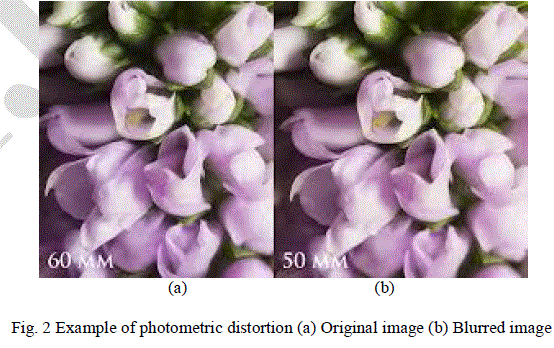
| It is a type of distortion in camera which is defined as the degradation in perceptual features that are known to attract visual attention, such as noise, blur, and blocking artifacts. Photometric distortion can be intrinsic owing of the acquisition device or extrinsic because of applications, such as lossy compression, transmission over error prone channels, or image enhancements. Quantifying the impact of these distortion types on perceptual quality is essential to the improvements or developments of new video or image applications, and hence has motivated the development of contemporary image and video quality metrics. For different camera systems, photometric distortion is the visible variations in brightness levels and colour across the entire displayed image. The variation can be the result of nonuniformity among individual camera properties or the post processing applications, such as compression. This type of variation in image is called as variational photometric distortion. |
 |
| B. Geometric distortions |
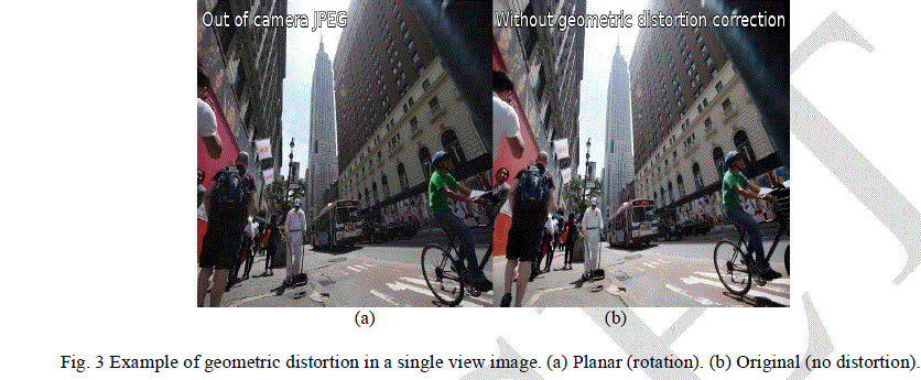
| There is one another type of distortion which is called as geometric distortions. In multiple camera system, a scene is captured by N cameras where we can change each individual camera’s position and orientation. These types of distortions are the visible misalignments, discontinuities, and blur in the processed image. These types of distortions could result from noticeable calibration errors between adjacent cameras, affine/linear corrections, and error in scene geometry estimations. In manually built multiple camera arrays, these errors could also result from the mismatch in the vertical and horizontal directions among images and irregular camera rotations. |
 |
SIMULATION |
| A. Calculation of Luminance |
| For color spaces such as XYZ, the letter Y refers to relative luminance. No computation is required to find relative luminance when it is explicit in a color representation in such spaces. Y = 0.2126 R + 0.7152 G + 0.0722 B (1) The formula reflects the luminosity function: the green light contributes the most to the intensity perceived by human eye, and blue light the least. In general, the coefficients are all positive, the green coefficient is largest and blue smallest, and the three form the middle row of the RGB-to-XYZ colour transformation matrix. For nonlinear gamma-compressed R'G'B' spaces as typically used for computer images, a linearization of the R'G'B' components to RGB is needed before the linear combination |
| B. Calculation of Contrast |
| Various definitions of contrast are used in different situations. Here, luminance contrast is used as an example, but the formulas can also be applied to other physical quantities. In many cases, the definitions of contrast represent a ratio of the type |
| The reason behind this is that a small difference is negligible if the average luminance is high, while the same small difference matters if the average luminance is low Michelson contrast (also known as the Visibility) is commonly used for patterns where both bright and dark features are equivalent and take up similar fractions of the area. The Michelson contrast is defined as |
| Where Imax and Imin representing the highest and lowest luminance. The denominator represents twice the average of the luminance. |
| C. Calculation of Spatial motion index |
| Geometric distortions in multiple view images are due to displacements or shifts at the pixel locations with respect to the reference image. For 2-D image, these displacements are comparable to spatial motion of single-view videos. |
| Hence, a motion model can be used to quantify geometric distortions. In this use of motion vectors to compute the pixel displacements relative o the reference image. |
| First, the motion vector |
| v = [Vm, Vn ] (5) |
| at a macroblock location [1+ms, 1+ns] of the distorted image J relative to the reference image I is computed over a search area of p× p. The values of displacement are then normalized leading to the relative motion inductor at [m, n] is computed as |
 |
| D. Calculation of edge base structural index |
| The two indices that are presented till now calculate the distortions in terms of changes in contrast and luminance and pixel displacements in an image. The two different distortion as photometric and geometric distortions may can cause loss in structural information. This type of information involves degradation in texture quality or lost image components on intersection or overlapping areas. Evaluating the SSIM over edge maps instead of the actual images leads to better correlation with subjective quality for SSIM. Spatial edges are defined as the locations of variations of intensity values and the relative intensity values at this point. When an image is blurred or quantized the locations of the spatial edges are preserved; however, the intensity values of these edges change. In geometric distortions, such as translations and rotations, the spatial edge locations change where there relative intensity is preserved. So by comparing the local edge information, we can get the loss of structural information because of both photometric and geometric distortions. To calculate the edge-based structural index, we reuse the mapped texture randomness index. For M × N total macroblocks, the index is computed as follows: |
 |
| E. Calculation for structural similarity index |
| We provide a more extensive set of validation as a result of algorithm we are using. The luminance of the surface of an object being observed is the product of the illumination and the reflectance. The structures of the objects in the scene are independent of the illumination. Consequently, to explore the structural information in an image, we wish to separate the influence of the illumination. We define the structural information in an image as those attributes that represent the structure of objects in the scene, independent of the average luminance and contrast. Since luminance and contrast can vary across a scene, we use the local luminance and contrast for our definition. |
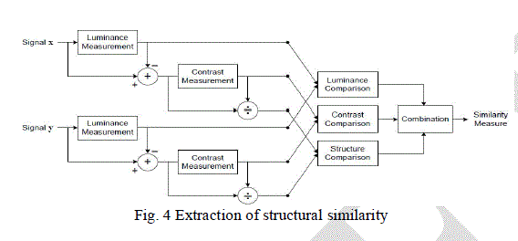
| Consider system diagram of the proposed quality assessment system, Suppose x and y are two nonnegative image signals, which have been aligned with each other . If we consider one of the signals to have perfect quality, then the similarity measure can serve as a quantitative measurement of the quality of the second signal. The system separates the task of similarity measurement into three comparisons: luminance, contrast and structure. First, the luminance of each signal is compared. Assuming discrete signals, this is estimated as the mean intensity: |
| The luminance comparison function l(x; y) is then a function of Ux and Uy. |
| Second, we remove the mean intensity from the signal. In discrete form, the resulting signal x-Ux corresponds to the projection of vector x onto the hyperplane defined by |
| We use the standard deviation (the square root of variance) as an estimate of the signal contrast. An unbiased estimate in discrete form is given by |
 |
| The contrast comparison c(x; y) is then the comparison of 6x and 6y. Third, the signal is normalized (divided) by its own standard deviation; so that the two signals being compared have unit standard deviation. The structure comparison s(x; y) is conducted on these normalized signals (x-Ux)=6x and (y -Uy)=6y. Finally, the three components are combined to yield an overall similarity measure: |
| S(x; y) =f(l(x;y);c(x;y);s(x;y)) (11) |
| An important point is that the three components are relatively independent. For example, the change of luminance and/or contrast will not affect the structures of images. In order to complete the definition of the similarity measure in Equation above, we need to define the three functions l(x; y), c(x; y), s(x; y), as well as the combination function f(¢). |
 |
| Structure comparison is conducted after luminance subtraction and variance normalization. Specifically, we associate the two unit vectors (x -Ux)=6x and (y -Uy)=6y, each lying in the hyperplane defined by Eq. (3), with the structure of the two images. The correlation (inner product) between these is a simple and effective measure to quantify the structural similarity. Notice that the correlation between (x -Ux)=6x and (y -Uy)=6y is equivalent to the correlation coefficient between x and y. Thus, we define the structure comparison function as follows: |
| The final image quality is calculated as the mean of all SSIM values and it is referred to as the mean SSIM. |
EXPERIMENTAL RESULTS |
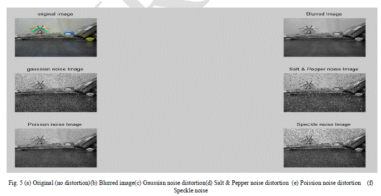
| We on the basis of calculated values of different features of images can compare images as follows |
 |
 |
CONCLUSION |
| We in this paper have discussed what are the features of images are. We discuss what the types of distortion and how they are affecting the quality image. We have given algorithm for comparisons so we get better quality image on the basis of comparison. |
References |
|