ISSN ONLINE(2319-8753)PRINT(2347-6710)
ISSN ONLINE(2319-8753)PRINT(2347-6710)
Afsal F Rahiman1, Maheswaran K2
|
Visit for more related articles at International Journal of Innovative Research in Science, Engineering and Technology
The paper proposes an independent hybrid power system that optimizes the output power with the varying input solar power. The hybrid system consists of photovoltaic, fuel-cell and battery as three sources which can supply the load individually or in tandem. Voltage control is used for regulating output voltage. Single phase and three phase systems are implemented and analysed. A multi input dc-dc converter is used to integrate the three dc input sources. Without the use of any transformers this converter gives us the advantage of smaller size lesser components and thereby reduction in cost. The dc-dc converter also gives us the advantage of bi-directional power flow with the storage element in this case the battery storage element. The single phase inverter is modelled with sinusoidal pulse width modulation control. The three-phase inverter is also modelled and two different control techniques are implemented, sinusoidal pulse width modulation (SPWM) and state vector pulse width modulation (SVPWM) and the quality of the obtained ac power is analysed. The above models are constructed using MATLAB/SIMULINK software
Keywords |
| Three input boost converter, Hybrid system, SPWM, SVPWM |
INTRODUCTION |
| This paper proposes a stand-alone power system that can be used for remote area applications. The power sources utilised are of renewable nature. The primary energy source selected is Photovoltaic (PV) systemas it appears as a quite attractive source for electricity generation as it is noiseless, pollution-free, scale flexibility, and causes little maintenance. To avoid the drawbacks faced by the Photovoltaic system like being dependent on sun irradiation level, ambient temperature, and unpredictable shadows, a PV-based power system should be supplemented by other alternative energy sources to ensure a reliable power supply. Fuel cells (FCs) are emerging as a promising supplementary power sources due to their merits of cleanliness, high efficiency, and high reliability. They are used to supplement the remaining power that cannot be supplied by the PV panels. A storage element is also incorporated for night periods and for dark periods during day time. Batteries are usually taken as storage mechanisms for the above purpose. They also help in smoothing output power, improving start up transitions and dynamic characteristics, and enhancing the peak power capacity.Here a PV/FC/Battery hybrid AC system is proposed. The combination of more than one power source brings the advantage of a hybrid system i.e. more reliability, redundancy and an overall energy efficient system. The system can be divided into two major components, the DC-DC converter and the inverter section.The DC-DC converter [1] hybridizes a PV, an FC and a bidirectional battery storage system, and also provides option for individual or combined supply of power from the three sources. Four switches are utilised to design the converter. Four different duty ratios are employed to control these switches to manage the power flow. Three different operating modes can be observed, based on the power obtained from the PV system. The inverter section is designed for both single phase and three phase output. The single phase inverter is controlled using SPWM technique and the three phase inverter is modelled for both SPWM and SVPWM and they are compared. The paper is divided into five sections. Section II discusses the system topology and the operation modes are discussed. The design parameters of the model is explained in Section III The converter simulation and input and output waveforms are presented in Section IV and the paper is concluded in Section V. |
 |
SYSTEM TOPOLOGY AND OPERATION MODES |
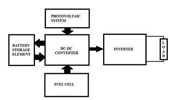
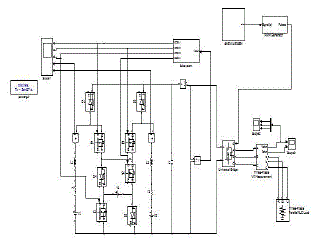
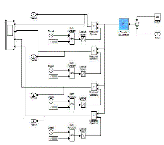
| A stand alone power system is proposed utilising hybrid power source structure for remote area applications. As shown in Fig 1, the proposed systemhas a dc-dc converter side that interfaces two unidirectional power sources and a bi-directional storage element, the inverter converts the dc out to ac and supplies it to the load, which can be a building or a machine according to the application. The circuit used for the single phase ac system is shown in Fig 2.The converter utilises four switches to control the power flow from the sources. The duty ratio of these four switches is controlled using a PI controller that compares the output dc voltage and reference voltage with sawtooth waveform to generate the required pulses. Three different operating modes are defined for the dc-dc converter based on the PV system. The single phase ac inverter is composed of four switches that are controlled using Sinusoidal Pulse Width Modulation. |
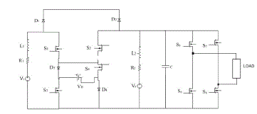 |
| As seen fromFig 2, the converter interfaces two input power sources V1and V2, and a battery denoted by VBas the storage element. The dc output from the converter is fed to the inverter input and ac output is obtained. The different operation modes of the dc converter can be briefly described as. |
| A. First Operation Mode |
| In this mode the sources V1 and V2 supply the load, the path chosen is S4-D3, the photovoltaic system combined with the fuel cell will supply the required power. In this operation mode, the control strategy is based on regulating one of the input sources on its reference power with its corresponding duty ratio, while the other power source is utilized to regulate the output voltage by means of its duty ratio. |
| B. Second Operation Mode |
| In this operation mode, two input power sources V1and V2along with the battery are responsible for supplying the load. In this operation mode, the control strategy is based on regulating both of the input power sources on their reference powers by means of their corresponding duty ratios d1and d2, while the battery discharge power is utilized to regulate the output voltage by duty ratio d4. |
| C. Third Operation Mode |
| In this operation mode, two input power sources V1and V2are responsible for supplying the load while the battery charging performance is accomplished.In this operation mode, if the total generated power of the input sources becomes more than the load power, the battery charging performance will be possible. With this control strategy, duty ratios d1and d2are utilized to regulate powers of the input sources, while duty ratio d3is utilized to regulate the output voltage through charging the battery by the extra-generated power. In all three operation modes, when one of the input power sources is not present to produce power, its corresponding duty ratio is set at zero, which results single power source operation for the converter. |
| D. Inverter Control |
| The single phase inverter is controlled by sinusoidal pulse width modulation for positive part of a sine wave switches S5 and S8 are turned on keeping S6 and S7 closed and for negative cycle switches S6 and S7 are turned on keeping S5 and S8 closed.Three phase inverter system is also modelled using SPWM and SVPWM pulse generating techniques for switch control. |
DESIGN AND SIMULATIONS |
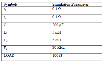
| There are five basic components for a boost converter i.e. DC Power Source, Power electronic switch, Inductor, Capacitor and gate signal generator. The components are designed [2] to obtain continuous conduction mode. |
| The duty ratio is given by [4][5]: |
 |
| The inductance value selected must be larger than the value obtained from above equation to obtain continuous conduction mode.Large values of capacitor and inductors are selected so as to get a ripple free DC component as output. |
| Inverter is simulated using four power electronic switches; these are controlled by the sinusoidal signal generated. The three phase system is also simulated and control is done by SPWM and SVPWM [6]. Three phase SPWM is obtained by generating three sine waves 120 degrees apart and feeding to PWM generator to get the required gate pulses which are then fed to the universal bridge containing three arms and six switches. SVPWM is modelled by generating a program that determines Vd, Vq and Vref by co-ordinate transformation, determining the principle time durations, determining the time durations which is the combination of the principle time durations of each of the six switches in the universal bridge. The output from the block is then fed to PWM generator block which supplies the gate signals to the switches in the universal bridge. The modelled system is analysed and compared. |
 |
MATLAB SIMULATION MODELS |
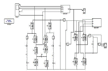
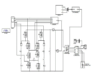
| Three different models are simulated in matlab for single phase ac system with SPWM control and three phase ac system with SPWM and SVPWM control techniques. The obtained graphs are shown in the next section. The graphs obtained for three phase system with SPWM and SVPWM are compared and result obtained is table 2. |
 |
 |
SIMULATION RESULTS |
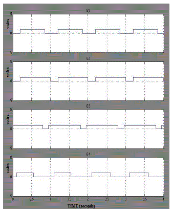
| The stand alone hybrid power system was simulated using MATLAB/SIMULINK for both single phase ac and three phase ac power output. The control signals for the dc-dc converter is generated using PI control technique as shown in Fig 6. The graphs show the gate signals applied to the switches. From the simulation result it is observed that the output voltage can be maintained at a particular value by selecting the mode of operation, also it is seen that the converter can be used to optimize the utilization of a photovoltaic dependant power system.The single phase ac output obtained is shown in Fig 8. The three phase ac output is obtained for both SPWM and SVPWM control techniques and shown in Fig 9 and Fig 10 respectively. Fig 11 and Fig 12 show the separate waveforms of each phase. |
 |
 |
| Three phase output waveforms are shown in Fig 9. andFig 10. The variation of ac output can be observed by looking at the graphs for the different inverter control techniques. The inverter output with SPWM has more harmonics and is not a smooth ac out whereas the ac output obtained by using SVPWM has much cleaner ac output waveform. |
 |
 |
CONCLUSION |
| A stand alone power system utilising a photovoltaic, fuel cell battery hybrid system is shown in this paper. The three dc sources are hybridised with a DC-DC boost converter having a unified structure. The converter hybridizesthe PV,FC, and a battery storage system. Four independent duty ratios of the converter facilitate power flow among input sources and the load. Three different power operation modes are defined for the converter. Single phase and three phase inverter systems are also modelled using SPWM and SVPWM control techniques. From the simulation it can be observed that the output voltage can be regulated with varying PV voltage. The three phase output voltages for two different inverter control techniques is compared and state vector pulse width modulation is observed to produce a better ac output waveform with lesser distortion. |
References |
|