ISSN ONLINE(2278-8875) PRINT (2320-3765)
ISSN ONLINE(2278-8875) PRINT (2320-3765)
Vijayakumar.R1, M.P. Mohandass2, D.Rajasindhu3, S.Angeline Sreeja4
|
| Related article at Pubmed, Scholar Google |
Visit for more related articles at International Journal of Advanced Research in Electrical, Electronics and Instrumentation Engineering
In a standalone operation of wind turbine generating system managing the condition under fluctuating wind and variation of load is very difficult task. Moreover, high reactive power demand makes it more challenging due to the limitation of reactive capability of the wind generating system. A Remote Area Power Supply (RAPS) system consisting of a Permanent Magnet Synchronous Generator (PMSG), hybrid energy storage, a dump load and a mains load is considered in this project. The hybrid energy storage consists of battery storage and a supercapacitor where both are connected to the DC bus of the RAPS system. An energy management algorithm (EMA) is proposed for the hybrid energy storage with a view to improve the performance of the battery storage. A synchronous condenser is employed to provide reactive power and inertial support to the RAPS system. A coordinated control approach is developed to manage the active and reactive power flows among the RAPS components. In this regard, individual controllers for each RAPS component have been developed for effective management of the RAPS components. Through simulation studies carried out using detailed model in MATLAB Simulink, it has been demonstrated that the proposed method is capable of achieving: a) effective management of the hybrid storage system, b) reactive power capability and inertial support by the synchronous condenser.
Keywords |
| Hybrid Energy Storage System, Permanent Magnet Synchronous Generator, Remote Area Power Supply, Battery and Supercapacitor. |
INTRODUCTION |
| Variable nature of wind and fluctuating load profiles make the operation of wind based power systems challenging, particularly when they operate in standalone mode. The random variation of wind speed leads to fluctuating torque of the wind turbine generator resulting in voltage and frequency excursions in the Remote Area Power Supply (RAPS) system [2]. Integration of an Energy Storage System (ESS) into a wind based power system provides an opportunity for better voltage and frequency response, especially during wind and load demand variations. The application of energy storage to a standalone power system can be used to fulfill one or more of the following requirements: |
| (1) To improve the efficiency of the entire RAPS system, |
| (2) To reduce the primary fuel (e.g., diesel) usage by energy conversion, and |
| (3) To provide better security of energy supply [3]. |
| The justification behind the integration of energy storage into a wind energy application is based on the factors which include total wind turbine inertia, low voltage ride through capability, power quality issues, etc. [4]. For a wind turbine based RAPS system, an ideal ESS should be able to provide both high energy and power capacity to handle situations such as wind gust or sudden load variations which may exist for a few seconds or even longer [5]. However, among all the energy storage options available, a single type of energy storage is not seen to satisfy both power and energy requirements of the RAPS system thus requiring the combination of two or more energy storage systems to perform in a hybrid manner [6]. The selection of an energy storage option requires good understanding of its operational characteristics. In general, battery and supercapacitor are seen to provide high energy and power requirements respectively. Therefore, the integration of a supercapacitor ensures a healthy operation of the battery storage by preventing it to operate in high Depth of Discharge (DOD) regions and to operate at low frequency power regions. Permanent Magnet Synchronous Generator (PMSG) offers many advantages but not limited to self excitation capability which allows operation at a high power factor and improved efficiency, gear-less transmission, high reliability, good control performance, Maximum Power Point Tracking (MPPT) capability, low noise emissions, etc. [16]. In this paper, the performance of the components of a hybrid RAPS system is investigated under fluctuating wind and variable load conditions. The schematic of the proposed RAPS system is shown in Fig. 1. The PMSG performs as the main source of energy while the hybrid energy storage together with the dump load perform as auxiliary system components to maintain the active power balance of the RAPS system. To provide enhanced reactive power and inertial support, a synchronous condenser is integrated into the RAPS system. |
| The existing work on remote area power supply systems with energy storage is summarized below. An isolated operation of a PMSG with a battery storage system is discussed in [7]. It only covers a RAPS system consisting of a PMSG and battery storage. A multilevel energy storage consisting of flow battery storage and a supercapacitor is explained in [8]. Different control strategies proposed for the battery-supercapacitor hybrid energy storage are discussed in [9]. In this paper, an entire RAPS system is modeled to evaluate the complete system performance as well as the performance of the individual components in relation to the voltage frequency and power sharing among the system-components. A coordinated approach for power management is proposed for the system components in the RAPS system, to operate the RAPS system during over and under generation scenarios. A power sharing strategy is formulated for battery energy storage and supercapacitor based on the demand-generation variations of the RAPS system [1]. The key objective of the proposed control methodology is to operate the hybrid energy storage in such a manner that battery storage is used to mitigate low frequency fluctuation and the supercapacitor is to mitigate high frequency fluctuation. An energy management strategy is presented. Reactive power management has been realised through integrating and operating a synchronous condenser in a coordinated manner with other energy resources of the RAPS system. |
II. CONTROL APPROACH FOR THE RAPS SYSTEM |
| In relevance to the RAPS system shown in Fig. 1, the active power flow has to be coordinated among the wind turbine generator, battery storage, supercapacitor and dump load which is given by (1). |
 |
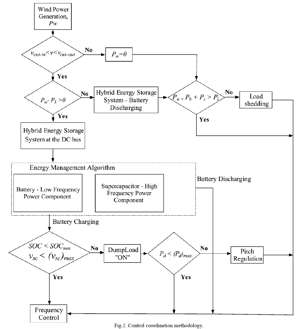 |
| Where, it is assumed that the hybrid energy storage is capable of providing the required power into the system. The control coordination approach discussed above has been realized by developing the control strategies for each system components of the RAPS system. It is assumed that the power outputs of wind system and hybrid energy storage are sufficient to supply the load demand at all time. In other words, emergency situations such as wind turbine generator operation below cut-in speed Vcut-inor above cut-out speed , have not been considered. In practical RAPS systems, a load shedding scheme can be implemented during an emergency situation where the reduced load is then supplied by the hybrid energy storage system. The reactive power sharing is made between the synchronous condenser and inverter as given by (2). |
 |
III. CONTROL ASSOCIATED WITH PMSG |
| As mentioned earlier, in the RAPS system shown in Fig. 1, the PMSG performs as the main source of energy and is inter-faced with an uncontrolled rectifier-inverter arrangement before connecting to the mains load. In this regard, control is developed for the Line Side Converter (LSC) and DC/DC converter which is presented in the proceeding subsections. |
A. Line Side Converter Control |
| The LSC is modelled as a voltage controlled voltage source inverter. The control objective of the LSC is to regulate the magnitude and frequency of the load side voltage. In this regard, vector control has been employed to develop the control associated with the LSC. The voltage balance across the filter of the LSC is expressed using (3). |
 |
| Where Va1,Vb1,Vc1- voltages at the inverter output, voltages at load side,ia,ib,ic- current through the filter circuit, and - filter inductance and resistance, respectively. These quantities are then transformed into a synchronously rotating d-q (direct and quadrature) coordinates with an angular velocity ωs. |
B. Control Strategy for DC/DC Converter |
| The DC link voltage of the RAPS system is regulated using a DC/DC converter (i.e., boost converter). The rectified voltage output,(vdc)unreg presents at the full converter diode bridge is a function (i.e., linearly proportional) of the generator speed,ωg. The outer control loop measures the DC link voltage, vdc which is compared with the reference DC link voltage, (vdc)ref and the error is compensated using a PI controller to generate the reference current through the inductor of the boost converter. |
IV. BATTERY STORAGE AND SUPERCAPACITOR |
| Nickel-Cadmium battery model given in [18] is employed in this paper. The capacity of the battery storage system reduces dramatically under high DODs. Therefore, in real life situations, it is vital to regulate the State Of Charge (SOC) of the battery within the safe limits SOCmin < SOC < SOCmax.In this paper, the battery storage capacity is estimated using (6) which is able to provide a fraction (or ϒ) of rated current of the load demand. |
 |
| where |
| ϒ- fraction of the rated current of the load demand, Irated —rated current of the load demand, t—time duration that battery provides power into the system and k—a fraction that defines the average discharge/charge current of the battery. |
| It is assumed that battery storage is used to supply 45 percent of the rated load current (i.e., ϒ=0.4) for the time-duration of 30 min (i.e.,t =30sec). To demonstrate how the size of the battery can be estimated, assume that the rated power of PMSG,(PPMSG)rated is 250 kW and the rated AC voltage, vrated is 400 V. The rated current of the PMSG can be calculated as follows: |
 |
| For this condition, the Amphere-hour (Ah) rating of the battery storage system can be estimated using (6) as below: |
 |
| Where Esc- energy rating of the supercapacitor and (Vsc)max and(Vsc)min - maximum and minimum operating voltages of supercapacitor respectively. To demonstrate how the size of the supercapacitor can be calculated, let us assume that the safe voltage operating limits of the supercapacitor is |
| 275 < Vsc < 375 |
| The size of the supercapacitor is estimated in the absence of wind power where the supercapacitor provides the rated power of PMSG,PPMSG (i.e., 250 kW) to mains load for a time-duration, say t = 10s. . For this condition, the capacitance value of the supercapacitor will be as below: |
 |
V. ENERGY MANAGEMENT ALGORITHM (EMA) FOR HYBRID ENERGY STORAGE |
| In this paper an energy management algorithm is developed and implemented between the battery storage and supercapacitor with a view to achieve the following objectives: |
| 1) To help maintain the power balance of the RAPS system, |
| 2) To improve the performance of the battery storage system by avoiding its operation with high frequency ripple currents and high rate of DODs. |
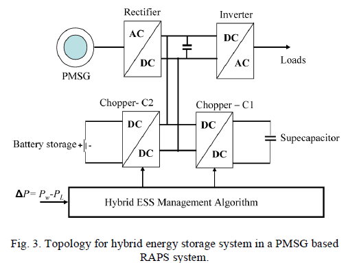
| This will relieve the battery stress and increase the battery life. Among several options of connection topologies, bidirectional buck-boost converters (or choppers), C1 and C2 in Fig. 3, have been used to interface both the supercapacitor and battery storage respectively. The energy management algorithm applied for both storage options have been developed to satisfy the above-stated objectives. |
 |
 |
VI. SYNCHRONOUS CONDENSER |
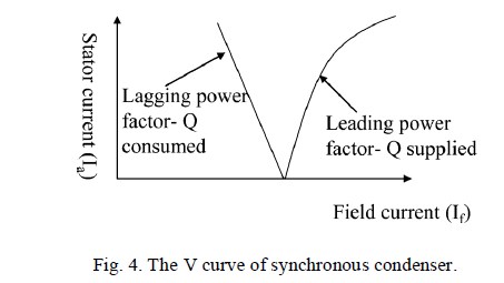
| In the RAPS system shown in Fig. 1, the PMSG inverter control may not be able to provide robust voltage control especially when it needs to serve reactive power loads. This is mainly due to the capacity limitation associated with the inverters. Moreover, the PMSG is fully decoupled from the power electronic arrangement (i.e., through rectifier and inverter arrangement). Therefore, the PMSG has no inertia contribution towards the inertial requirement of the entire RAPS system. In this regard, to provide enhanced reactive power together with inertial support, a synchronous condenser can be incorporated into the RAPS system. The operational characteristics of a synchronous condenser is shown in Fig. 4. In this paper, the synchronous condenser is used to operate at leading power factor region to supply reactive power into the RAPS system. For the simulation purposes a capacitor bank is used. |
VII. DUMP LOAD |
| The dump load is coordinated with the hybrid energy storage system to maintain the active power balance of the system. In practical RAPS systems, a dump load can be a space-heating or water-heating system. In this paper, the dump load is represented by a series of resistors which are connected across switches. The resistors operate at zero crossings of the load side voltage to ensure minimum impact on the system voltage quality. |
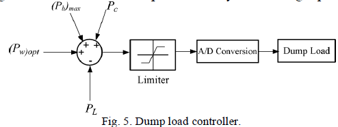 |
| A simplified control schematic diagram of the dump load controller is shown in Fig. 5. |
 |
VIII. SIMULATION AND RESULT |
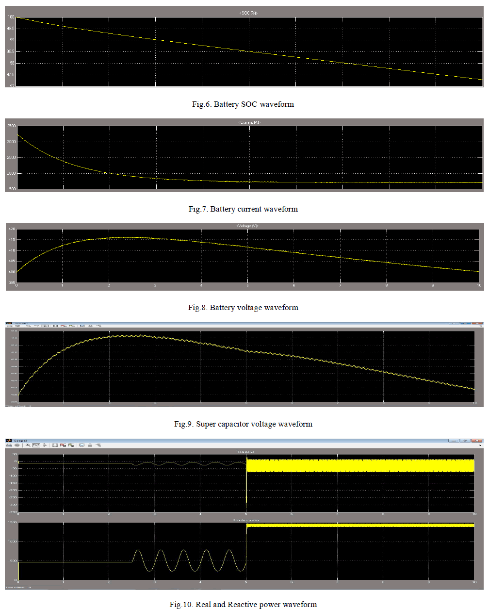
| In order to verify the analysis and specification, the simulation investigation is carried out by using MATLAB simulink. The simulation time step used was 10 micro-seconds to capture the true behaviour of the system components. The DC side equivalent capacitor is set to 1.8mF. Besides, 70F super capacitor and 180Ah battery are selected to verify this control strategy. The terminal voltage of super capacitor is 400V and battery terminal voltage is also 400V. The Battery, State Of Charge (SOC), current and voltage waveforms are shown below figures (i.e. from Fig.6. to Fig.8.). Fig.9. shows the supercapacitor voltage waveform. The real and reactive power of the system is given in the Fig.10. |
 |
IX. CONCLUSION |
| This paper has investigated the standalone operation of a PMSG with a hybrid energy storage system consisting of battery storage and a supercapacitor, a synchronous condenser and a dump load. The entire RAPS system is designed and the simulation is done by MATLAB simulink. The suitability of the adopted control strategy for each system component is evaluated in terms of their contributions towards regulating the load side voltage and frequency. The investigation has been carried out in relation to the voltage and frequency regulation at load side, DC bus stability, and the performance of storage system. From this it can obtain more efficiency in RAPS system and hybrid storage systems. The supercapacitor absorbs the ripple or high frequency power component of demand generation mismatch while leaving the steady component for the battery storage. The supercapacitor helps in avoiding battery operation in high rate of depth of discharge regions. The integration of the synchronous condenser, it has been to be accurate that the RAPS system is able to maintain the load voltage within acceptable limits for all conditions including the situation when reactive power demand becomes very high. |
References |
|