ISSN ONLINE(2319-8753)PRINT(2347-6710)
ISSN ONLINE(2319-8753)PRINT(2347-6710)
Deepak G1, MMM Patnaik2 Shivasharanayya swamy3
|
| Related article at Pubmed, Scholar Google |
Visit for more related articles at International Journal of Innovative Research in Science, Engineering and Technology
One of the most important cardiovascular diseases is atherosclerosis, which often leads to narrowed (or stenosed) arteries that obstruct the flow of oxygen rich blood. In the case of coronary arteries, this may limit the oxygen delivery to the heart muscle and can lead to a heart attack. The blood flow through these narrowed arteries is often restored by inserting folding structures, named Stent. A Stent is expandable tube-like device that is inserted into a natural conduit of the body to restore a disease-induced localized stenosis. The aim of this study is to provide a computational approach for evaluating the effect of Stent materials on biomechanical outcomes and the deployments of Stents in different condition. A linear Finite Element (FE) procedure is carried out using the Generic Stent geometry, to quantitatively predict the effect of mechanical properties such as stress, strain and density of these biomaterials on Stent behavior during the deployment. A quantitative comparison is made for exploring the effect of different materials on the deployment of Stent. The study is considered significant in understanding the role for Stent materials affect on the biomechanical responses to the coronary Stenting.
Keywords |
| Stents, linear Finite Element. |
INTRODUCTION |
| A Stent is an expandable tube-like device that is inserted into a natural conduit of the body to restore a diseaseinduced localized stenosis. Nowadays, many of the clinical procedures are required in very wide range of medical activities and it is the new frontier in the research of medical devices design. Stents have to overcome a wide range of technical and design problems related to miniaturization [1]. Therefore, a Stent provides an excellent answer to the increasing trend for less invasive and therefore less traumatic procedures. The study of the material and the geometrical properties of the Stent can provide useful indications on its performance and on its interaction with the target vessel [2]. |
II. DESIGN OF CARDIOVASCULAR STENT IMPLANT |
| The variables below define the key aspects of Stent geometry as shown in fig.1[3]. |
 |
| Fig.1Unit cell Stent geometry as cut state |
a. STENT DESIGN INPUTS |
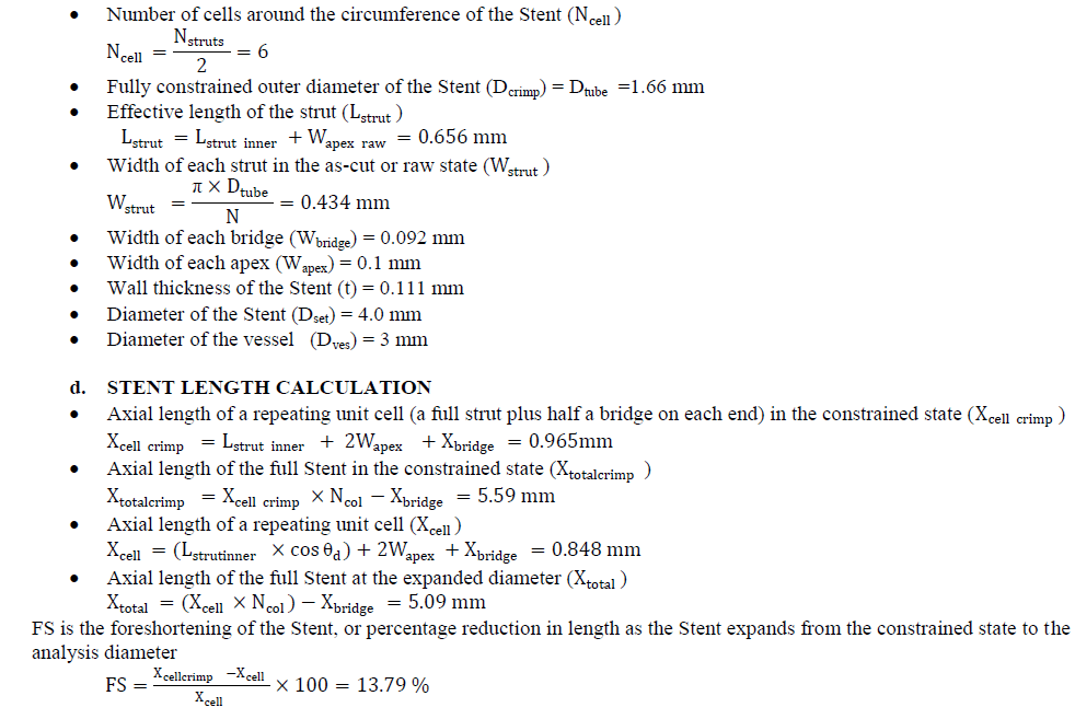
| ïÃâ÷ Number of columns of struts along the length of the Stent (Ncol) = 6 |
| ïÃâ÷ Number of columns of struts around the circumference of the Stent (Nstruts) = 12 |
| ïÃâ÷ Outer diameter of the tube from which the Stent is fabricated (Dtube) = 1.66 mm |
| ïÃâ÷ Wall thickness of the tube from which the Stent is fabricated (t) = 0.111 mm |
| ïÃâ÷ Length of a strut, measured between the quadrants of the inner arcs of opposite apices (Lstrut inner) = 0.56 mm |
| ïÃâ÷ Width of an apex in the raw (Wapex) = 0.1 mm |
| ïÃâ÷ Axial gap between adjacent columns of struts (Xbridge) = 0.2 mm |
| ïÃâ÷ Width of a bridge element in the raw (Wbridgeraw) = 0.092 mm |
| ïÃâ÷ Number of bridges around the circumference of the Stent (Nbridges) = 2 |
b. STENT PROCESS INPUTS |
| The variables below relate to various assumptions regarding the manufacturing processes used to fabricate the Stent. |
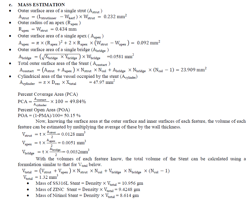
| ïÃâ÷ Effective kerf width between struts when fabricated (Wkerf) = 0.025 mm |
| ïÃâ÷ Total amount of material removal from feature during finishing operations (Mwidth) = 0.036 mm |
c. STENT DIMENSION CALCULATION |
| This section explains the calculations of a number of derived Stent characteristics and dimensions |
 |
 |
III. SELECTION OF MATERIALS |
| The material used for human cardiovascular Stent implants are conventional materials, with heavier in density, not economical and unstable. It is observed that implant materials are affecting the coronary vessel where the failure of implant is maximum due to wear, corrosion and fatigue. These problems are due to improper material selection. Therefore in this paper work, an economical, low density and stable materials is selected. Here Stent is subjected to various load conditions to conduct the FEA. By carrying out linear static analysis of the Stent strength and expansion behavior can be determined [4]. Table 1 gives the properties of good materials that can be used for Stent. The Stent material should have to obey the following requirement for its usage. 1. Biocompatibility. 2. Density. 3. Flexibility. 4. Ability to support the duct wall. |
 |
| The above materials listed in table -1 have less mass for the selected geometry of the stent and meeting the entire requirement that a stent material should have. Hence they are selected for carrying the FE analysis. |
IV. FINITE ELEMENT ANALYSIS OF THE STENT |
a. FINITE ELEMENT ANALYSIS |
| FEA consists of a computer model of a material or design that is stressed and analyzed for specific results. It is used in new product design, and existing product refinement. Modifying an existing product or structure is utilized to qualify the product or structure for a new service condition. In case of structural failure, FEA may be used to carry out the design modifications/optimization [5]. Finite Element Analysis can be carried out by following the three stages. The flow diagram of the FE analysis is shown in fig.2. |
b. MODELING METHODOLOGY |
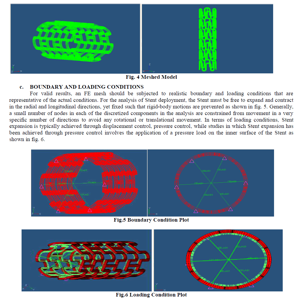
| The first sketch in the Stent part is the strut sketch. This strut sketch is carefully constructed such that its entire feature must be obtained. The sketch is fully constrained, which can balance the challenges to achieve the Stent models in CATIA VR20.The sketch is created on the front plane, and the first geometry features placed in the sketch form a rectangle comprised of construction lines. The bottom horizontal line can be anchored at one end to the origin, and the top horizontal line is placed at a distance of strut above the bottom line. These two lines define the bounds of the strut in the vertical or circumferential direction, and the spacing between them will vary depending upon the diameter of the Stent. Vertical lines are then placed at the left and right, forming a construction rectangle that will bind the strut at all times. Note that the horizontal length of the construction rectangle is not defined, but rather it is dependent upon the defined length of the strut. It should also be noted that the expanded configuration assumes that the strut will be perfectly straight, while in reality an expanded strut bend with a curvature which is too complex to represent in this simple model. Finally the created 3-Dimensional model of Generic Stent is shown in fig.3.meshing has done in hypermesh commercial software, the model shown in fig .4. |
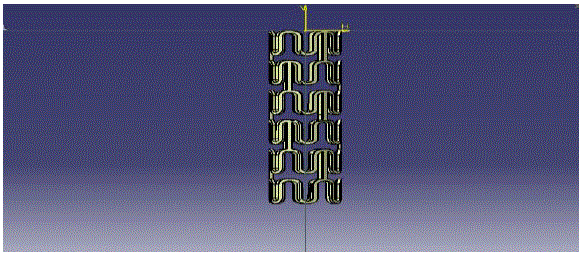 |
| Fig. 3 Stent Implant model |
 |
IV. RESULTS AND DISCUSSION |
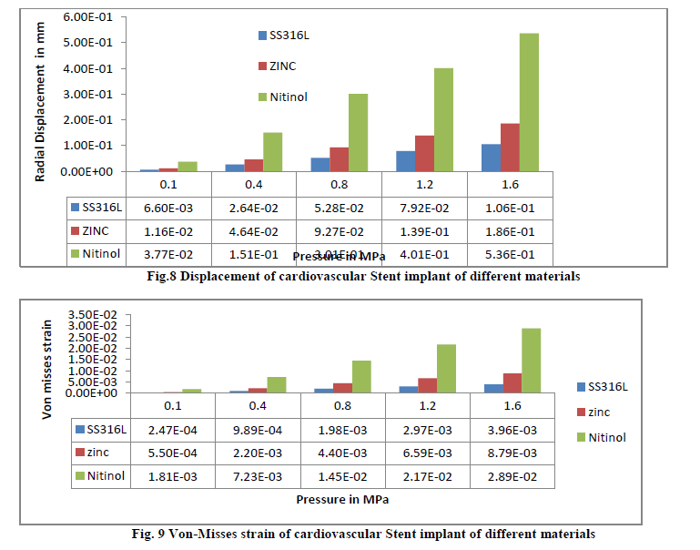
| The Linear Static analysis is carried on Stent implant model considering the pressure loads exerted by human body and pressure exerted while implanting the Stent though the body viz 0.1MPa, 0.4MPa, 0.8MPa, 1.2MPa, and 1.6MPa. The results are tabulated (Table 2, 3 and 4) and discussed for the realistic use and for the materials listed in Table 1. |
 |
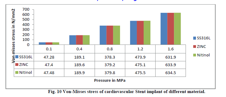
| The von misses stress developed for considered materials when subjected to the pressure loads of 0.1MPa, 0.4MPa, 0.8MPa, 1.2MPa, and 1.6MPa are shown in fig.10. The maximum stress is being observed that 634.5 N/mm2 for Nitinol under 1.6MPa and a least stress of 631.9 seen for the SS316L under load of 1.6MP |
 |
 |
V. CONCLUSIONS |
| Displacements obtained for the materials Nitinol, SS316L and Zinc are 0.535mm, 0.105mm and 0.185mm respectively for 1.6MPa pressure load. Therefore Stent materials most suitable for getting more radial displacement are Nitinol and SS316L. These materials can be recommended as future cardiovascular implant materials. The mass of Generic Stent Model with SS316L, Zinc and Nitinol is 10.95 gm, 9.4248 gm and 8.514 gm respectively. As the Stent made out Zinc and Nitinol are showing less mass for the same configuration and geometry, these can be used as future cardiovascular implant materials. |
References |
|