ISSN ONLINE(2278-8875) PRINT (2320-3765)
ISSN ONLINE(2278-8875) PRINT (2320-3765)
Savita M Shaka1, Prashant R.T1, Vani R.M2 and Hunagund P.V1
|
| Related article at Pubmed, Scholar Google |
Visit for more related articles at International Journal of Advanced Research in Electrical, Electronics and Instrumentation Engineering
Wideband antenna is highly demandable due to the dynamic development in the wireless technology. In this paper, we propose a new design of rectangular microstrip antenna based on the EBG Cell loading technique. By incorporating the Uniplanar Electromagnetic Band Gap (EBG) Cells on the ground plane of the rectangular microstrip Antenna, the enhanced performance of the antenna can be enhanced. Here we have studied and compared Conventional Rectangular Microstrip Antenna (CRMA) antenna performance with and without EBG cells. Comparison result shows that the bandwidth of CRMA is enhanced by loading EBG cells and the bandwidth increases to 62.45%. Also with EBG cells there is reduction in the back lobe radiations.
Keywords |
| Rectangular Microstrip Antenna, Uniplanar Electromagnetic Band Gap (EBG), parameters, Bandwidth. |
INTRODUCTION |
| Recent advances in wireless communications, radar, satellite and space programs have introduced tremendous demands in the antenna technology Among the various types of antenna, Microstrip antennas are of special interest because of their light weight, low profile, compactness and compatibility with integrated circuits, though they suffer from some drawbacks e.g., narrow bandwidth, low gain and excitation of surface waves[1]. To overcome these limitations, new methods are still being explored and the interesting features of Electromagnetic Band Gap (EBG) structure have attracted the antenna researchers. Usually, the Electromagnetic Band Gap (EBG) cells are periodical structures composed of metallic or dielectric elements [2, 3]. Addition of defects into the periodical structure, exhibits the ability to reject the propagation of the electromagnetic waves whose frequency is included within their frequency band gap and to open localized electromagnetic modes inside the forbidden frequency band (Yablonovitch, 1987)[4]. EBG always referred as high impedance surface that increase antenna surface efficiency by suppressing the unwanted surface wave current. Suppression of surface waves excitation helps to improve antenna’s performance such as, it reduces backward radiation [5,6]. In this study, CRMA with uniplanar EBG cells in the ground plane is considered and the parameter such as width of the slot of uniplanar EBG cell is varied & the performance is observed. |
ANTENNA DESIGN |
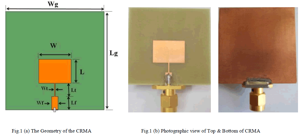
| The CRMA is designed and fabricated on low cost glass epoxy substrate of relative permittivity with εr=4.4, h=1.6mm with length of the patch L=11.33mm & width of the patch W=15.24mm. The radiating patch is fed by microstrip feed line Lf50=6.187mm & Wf50=3.06mm to match the impedance and quarter wave transformer Lt=4.922mm & Wt=0.5mm is used and ground plane of (40mX40mm) is considered for the design. The geometry of the CRMA is as shown in Fig1 (a). The photographic top and bottom view of the CRMA is as shown in Fig.1 (b). |
 |
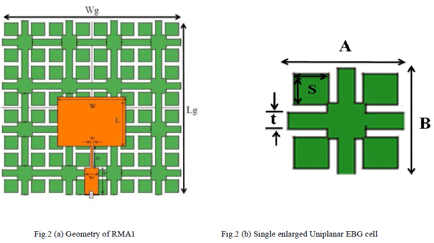
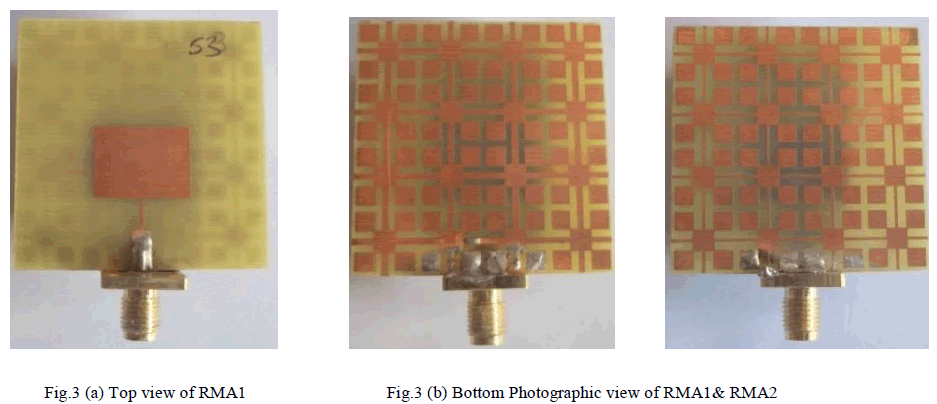
| Now we replace the conducting ground plane with the uniplanar EBG cells and the study is made for bandwidth enhancement. The geometry of the antenna with uniplanar EBG cells is shown in the Fig. 2(a). The enlarged view of the EBG cell is shown in the Fig. 2(b). There are 4x4 EBG cells with dimension of 9mmx9mm and a spacing g=0.75mm, the other parameters s=3mm and‘t’ are shown in Fig. 2(b). The parameter‘t’ is varied from 1.5mm to 0.5mm and the performance of the antenna has been studied. The antenna with uniplanar EBG in which t=1.5mm is treated as RMA1. The antenna with EBG in which t=0.5mm is treated as RMA2. The characteristics of these antennas are studied & compared with CRMA. Also the photographic view of the antenna with Uniplanar EBG cells is shown in Fig. 3(a) & 3(b). |
 |
 |
EXPERIMENTAL RESULTS |
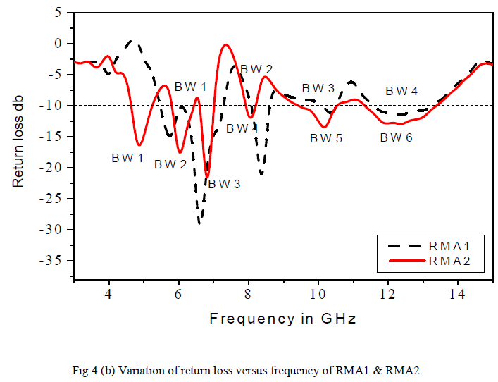
| The characteristics of proposed antennas have been experimentally measured with Vector Network Analyzer (Rohde & Schwarz, Germany make ZVK model 1127.28651).The variation of return loss versus frequency characteristics of proposed antennas, CRMA, RMA1 & RMA2 are shown in Fig.4 (a) & 4(b). The antenna with EBG i.e., RMA1 & RMA2 are giving multifrequency with increase in bandwidth. |
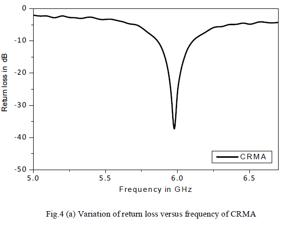 |
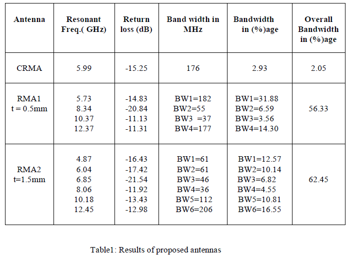
| From the figure 4(a), it is found that, the antenna CRMA resonates at f=5.99GHz. From this figure 4(b), it is found that, the antenna RMA1 operates between 5 to 13 GHz and gives a four bands with f1 = 5.73GHz, f2 = 8.34GHz, f3= 10.37GHz and f4= 12.37GHz . Similarly RMA2 operates between 4GHz to 13GHz and gives six bands with f1= 4.8GHz, f2=6.04GHz, f3=6.8GHz, f4=8.0GHz, f5=10.1GHz and f6=12.4GHz. So the overall bandwidth measured for RMA1 is 56.33% & for RMA2 is 62.45%. All the results are reported in table1. |
 |
 |
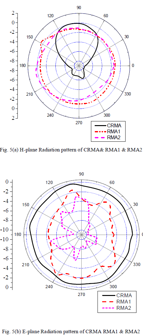
| The radiation patterns of the designed antennas at the resonant frequencies are also measured and plotted. For the measurement of radiation patterns, the antenna under test (AUT), i.e. the designed antennas and standard pyramidal horn antenna are kept in the far field region. The received power by AUT is measured from 00 to 3600 with the rotational motion at steps of 100 each. The H-plane patterns of CRMA, RMA1 & RMA2 are shown in fig. 5(a).The E-plane patterns of CRMA, RMA1 & RMA2 are shown in Fig. 5(b).From the radiation patterns it is observed that the antenna RMA2 has more reduction in backlobe radiations compared to RMA1 & CRMA. This shows the back lobe radiations are reduced with uiplanar EBG structure compared to CRMA. |
 |
CONCLUSION |
| The paper investigated the bandwidth improvement of Rectangular microstrip antenna by using Uniplanar EBG cell on the ground plane of the antenna. Also the antenna with EBG operates in mulitibands with enhancement of bandwidth to 62.45% compared to conventional antenna (CRMA). By observing the radiation patterns, it is clear that there is backlobe reduction with EBG structure. These antennas may find application in wireless communication system. |
ACKNOWLEDGMENT |
| The authors would like to convey thanks to the department of science & technology (DST) government of India, New Delhi, for sanctioning vector Network analyzer to this department under FIST project. |
References |
|