ISSN ONLINE(2278-8875) PRINT (2320-3765)
ISSN ONLINE(2278-8875) PRINT (2320-3765)
Chinchu G. Nair1, Prof. A.K. Prakash2, Mr. KuruvillaGeorge3
|
| Related article at Pubmed, Scholar Google |
Visit for more related articles at International Journal of Advanced Research in Electrical, Electronics and Instrumentation Engineering
Antenna is a device that can transmit or receive radio waves. TEM horn antenna is a wideband antenna having many applications in fields such as EMI testing, radar, UWB communication etc. This antenna consists of two triangular metal plates and a feeding structure. Although the shape of the antenna resembles to a horn antenna the radiation mechanism is different from that of a typical horn antenna. Also, horn antenna differs from TEM horn in terms of its inability to support TEM mode of propagation. Here, we conduct a study on the basic radiation mechanism of TEM horn antenna. This antenna can be viewed as a parallel plate transmission line. The design considerations of this antenna are also discussed. Simulation of a TEM horn antenna according to the design is implemented in HFSS and the results are provided.
Keywords |
| TEM horn antenna, Parallel plate transmission line, radiation pattern, modes of propagation. |
INTRODUCTION |
| Antenna is any device which can transmit or receive electromagnetic waves. Antenna is a vital part in any communication system. Depending on the application its requirements will vary. Antennas are generally categorised as wideband and narrow band based on their frequency range of operation. Owing to its better performance in terms of data rate and security, wideband antennas are preferred for communication especially for UWB applications. In this paper we are discussing TEM horn antenna which comes under the class of wideband antennas. |
| A combination of two triangular metal plates separated by an angle could be used as a basic TEM horn antenna. This antenna is applicable in EMC experiments, broadband communications, as feed for reflectors and in radars. TEM horn is widely preferred because of its wideband, high gain, low cross polarization, directional radiation and low dispersion characteristics. But, its large size is a challenge in many applications. TEM horn resembles to a horn antenna in terms of its shape, but unlike horn antenna the TEM horn supports TEM mode of propagation. In TEM mode the electric and magnetic fields are perpendicular to each other and are transverse to the direction of propagation of the wave i.e. Hz=0 and Ez=0 . No single conductor guiding system can support TEM mode. At least two conductors are required for the propagation of TEM wave. Coaxial cables, parallel plate transmission lines, strip line and microstrip can support TEM mode. TEM horn antenna can be considered as a parallel plate transmission line. This study investigates the radiation mechanism of TEM horn and the design considerations. |
| This paper is organised as follows: SectionII investigate the related works in this field. Section III discusses the basic radiation mechanism of TEM horn antenna. SectionIV deals with the design of TEM horn antenna followed by simulation of the antenna and its results in section V.Section VI concludes the survey with inferences drawn from the study and the results obtained from the simulation. |
RELATED WORKS |
| There are many papers on TEM horn antenna. But the literature concerning its radiation mechanism and design are few. TEM horn can be viewed as a parallel plate transmission line. A typical TEM horn antenna is shown in fig. 5. The upper and lower plates of this antenna act as the transmission line. Here, the transmission lines are not parallel but, tapered. The tapering provides gradual impedance transition. TEM horn is similar to patch antenna in the sense that, it is also a parallel plate transmission line. The dielectric material in the case of TEM horn is air. |
| Girishkumar and K.P. Ray, 2003[9] and Constantine A. Balanis, 2007 [3] discussed the fundamentals of Microstip patch antennas. Microstip patch antenna consists of a patch at one side of a dielectric and a ground plate on the other side. Radiations occur in patch as a result of the fringing field between the patch and ground plane. Direction of maximum radiation in the case of patch antenna is along the normal to the ground plane. The text book also provided the necessary design equations and discussed about the E-plane and H- plane patterns. |
| R. Todd Lee and Glenn S. Smith, 2004 [5] gives a design guideline for the transverse electromagnetic (TEM) horn antenna. The basic antenna consists only of two triangular metal plates and a feeding structure. Neglecting the feeding structure, the horn is described completely by only three variables: α, β, and s. α is the angular width of each plate, β is the angular separation between the two plates, and s is the length, measured from the drive point to a corner of the plate as shown in fig. 5. The paper shows some graphs for the possible values of α, β and s to keep the value of characteristic impedance to be in the desired range. |
| Many experiments are going on in the field of TEM horn antenna. The triangular plate can be either linear or exponentially tapered. Linearly tapered structure is easy to construct whereas, exponential tapering gives better impedance matching.S. Bassam and J. Rashed-Mohassel in their work [6], proposed a chebyshev tapered horn antenna. This antenna could achieve good directivity and wide bandwidth. Another modification by A. R. Mallahzadeh and F. Karshenas [7] suggest that, an arc curved at the edge of the horn can improve bandwidth.Adel Elsherbini, and Kamal Sarabandi in their work [8], suggests a more simple method of improving the bandwidth with reduced size of the antenna by providing an inductive shorting trace. They put forward a modified horn antenna named electrically narrow very low profile (ENVELOP) antenna for low frequency radars and diversity communication applications. |
RADIATION MECHANISM OF TEM HORN |
| Radiation mechanism of TEM horn is quite different from that of an ordinary horn antenna. The direction of maximum radiation for a normal horn antenna is along its axis whereas, for TEM horn it is along the normal to the axis. Also, normal horn antenna cannot support TEM mode of propagation as it requires a centre conductor. Radiation mechanism of TEM horn can be explained with the help of parallel plate transmission line. A parallel plate transmission line model is shown in Fig.1. |
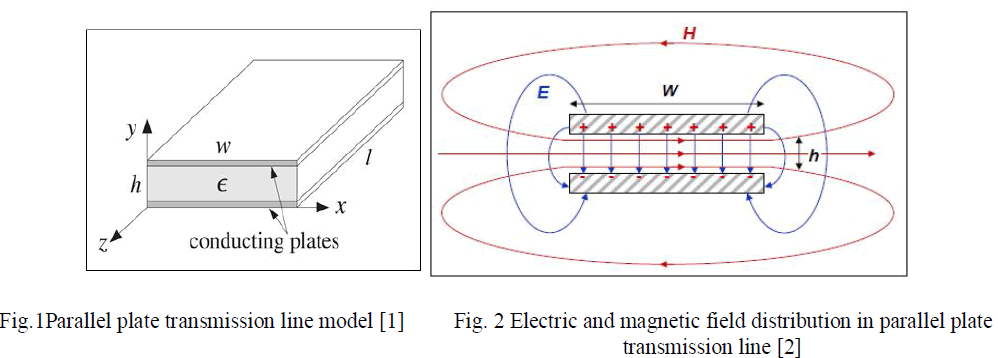 |
| The width of the line is w and its length is denoted as l. A dielectric substrate having dielectric constant Ãâ°Ã⺠is placed in between the plates. The separation between the plates is h. |
| With the introduction of a source to the transmission line, one plate attains positive potential and other plate becomes negative potential. The electric and magnetic fields will be as shown in Fig. 2. Electric field start from positive potential and ends at negative potential. Magnetic field will always surround the current carrying conductor. If the voltage source is sinusoidal then the electric field will also be sinusoidal with a period equal to that of the applied source. The time varying electric and magnetic field create electromagnetic waves which travel along the transmission line. At the open end of the transmission line free space waves are formed by connecting open ends of the electric field lines. This radiated wave will persist in the air even if the source is ceased to exist [3]. |
| TEM horn antenna can be viewed as a parallel plate transmission line. It consists of two triangular metal plates. But here we consider a triangular plate slanted over a ground plane. The structure of the antenna is shown in fig. 3. |
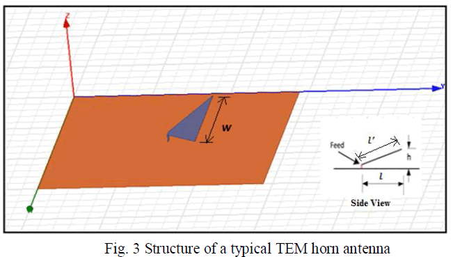 |
| We are particularly interested in a TEM horn with a ground plane as in fig. 3. The antenna is fed with a coaxial cable of 50Ω characteristic impedance at the centre of the ground plane. Dimension of the aperture is ïÿýïÿý × Ã¢ÃâÃŽ . Length of the plate is l. |
| The triangular plate and the ground plane can be considered as the upper and lower plate of a parallel plate transmission line. The radiation of TEM horn antenna from the front is shown in Fig. 4. |
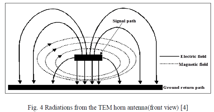 |
| At the open ends, electric field starts from the triangular plate and ends at ground pane as shown in fig. 4. Unlike waveguides, the parallel plate transmission line does not have the side walls. Therefore, radiation could occur from all the three sides. The resultant direction of maximum radiation is along normal to the horn axis i.e., along Z direction. The ground plane reflects all the backward radiations and thus provides better directivity along positive Z direction. |
DESIGN OF TEM HORN |
| The design of TEM horn could be found in the works done by R. T. Lee and G. S. Smith [5]. There, they have considered an antenna composed of two triangular metal plates and a feeding structure. The basic antenna structure is given in Fig 5. |
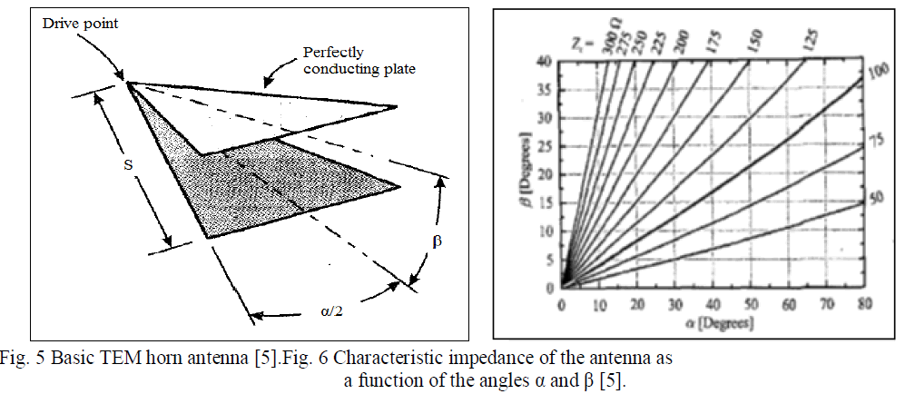 |
| α is the angular width of the plates, β is the angular separation between the plates and s is the slant length of the plate. In our work, we followed this design criterion with an image plane along the axis of the antenna as shown in Fig. 3. Characteristic impedance of the antenna is a function of the angles α and β. Fig. 6 shows the relationship between these angles and the characteristic impedance. In order to avoid reflection, the characteristic impedance of the antenna should match to the impedance at the feeding point. Usually the feed will be a 50Ω coaxial cable. |
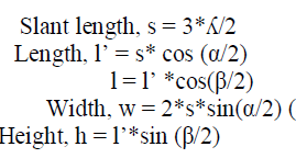
| For our study we considered α = 80° and β = 15° based on the observation made from the graph in Fig. 6. The slant height is taken as ÃÅ ÃŽ, i.e. the wavelength. Then the dimensions of the antenna becomes as follows: |
 |
SIMULATION RESULTS |
| The value of α and β for characteristic impedance 50Ω is selected from the graph to be α =800 and β =150. If the centre frequency is chosen as 2GHz then,ÃÅ ÃŽ=150mm. A tem horn antenna as shown in Fig. 3 is simulated in HFSS and the results are shown below. The dimensions of the antenna are given in the table. Ground plane of the antenna is oriented in the XY plane. |
 |
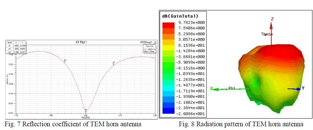 |
| The antenna is designed for 2GHz frequency. From the reflection coefficient plot it is clear that the antenna could resonate at 2GHz. The bandwidth of the antenna is 175 MHz. The radiation pattern of the antenna is shown in fig. 8. The direction of maximum radiation is towards the Z direction i.e., along the normal to the TEM horn. This antenna shows a maximum gain of 9.7 dB. Impedance matching could improve the bandwidth of the antenna. |
CONCLUSION |
| This paper attempts a study on the radiation mechanism of TEM horn antenna a popular wideband antenna, and its design considerations. TEM horn consists of two triangular metal plates. It can be considered as a parallel plate transmission line with three slots. The radiations from each slot create a pattern along the direction normal to horn axis. In our work, we considered the TEM horn antenna with an image plane. This antenna can support TEM mode of propagation, whereas ordinary horn antenna cannot. Design criterion of Tem horn antenna is also discussed. According to the design a TEM horn is simulated in HFSS and the results are provided. |
| From the simulated results it is clear that the antenna resonate in the designed frequency and the maximum radiation is directed normal to the horn axis. The gain of the antenna is found to be 9.7dB. But, the bandwidth of the antenna is poor and cannot be applicable to UWB applications. There are many modifications in literatures to improve the bandwidth to make the antenna suitable for wideband applications. Frequency range of operation of the antenna could be improved by better impedance matching techniques. TEM horn is widely preferred for airborne applications because its pattern is directed along the normal to horn axis, which could point to ground while the aircraft is flying. |
References |
|