ISSN ONLINE(2278-8875) PRINT (2320-3765)
ISSN ONLINE(2278-8875) PRINT (2320-3765)
Jaya S. Lahane1, Meera A.Khandekar2
|
| Related article at Pubmed, Scholar Google |
Visit for more related articles at International Journal of Advanced Research in Electrical, Electronics and Instrumentation Engineering
This paper is a case study, involving mathematical modeling of boiler and heat exchanger pilot plant by System Identification procedure. This is done by using System Identification Toolbox. Some fundamental control oriented issues such as System Identification, mathematical modeling and controller designing by using basic control strategies are discussed in it. First of all data is acquired from boiler and heat exchanger set-up. This data is used to obtain mathematical model with the help of System Identification Toolbox available in MATLAB. Transfer function model is obtained from System Identification and controller response is observed for this model. A conventional PID controller is designed and controller performance is studied
Keywords |
| System Identification, Matrix Laboratory (MATLAB), Mathematical model, Boiler and Heat Exchanger |
INTRODUCTION |
| System Identification is an experimental method to construct models from input and output data. The model should be able to describe the behavior of the process around an operating point. The model will be constructed with the help of the System Identification Toolbox in MATLAB. The goal is to give experience of how to use system identification to devise models. |
| Controller designing is done for this model. A conventional PID controller is designed from process reaction curve. Experimentation is done on Boiler and Heat Exchanger set up. Open loop experimentation is done to obtain data of heat exchanger. The set-up is operated in open loop mode to obtain process reaction curve. Process reaction curve is used for finding controller parameters. A PID controller is designed by using controller parameters. |
| Literature Survey: 1965 is called as birth year for System Identification theory in control systems because of publication of two seminal papers i.e. (Ho and Kalman, 1965) and (Astrom and Bohlin, 1965). These two papers are responsible for development of two Identification techniques i.e. subspace Identification and prediction error Identification that dominate the field today. In 1970, Box and Jenkins published their book,”Time Series analysis, forecasting and control” which gave major impetus to applications of Identification. In 1974, the survey paper by Astrom and Eykhoff and special issue on System Identification and time series analysis published by the IEEE Transaction on Automatic Control in December 1974. In 1978 first attempt to System Identification as an approximation theory is done by (Anderson et al., 1978; Ljung and Caines, 1979). |
| As it turns out, the research on bias and variance error moved remarkably swiftly from the characterization of parameter errors to that of transfer function errors, thanks to some remarkable analysis of Ljung based on the idea of letting the model order go to infinity (Ljung, 1985, Wahlberg and Ljung, 1986). One can tune these design variables towards the objective for which the model is being identified (Gevers and Ljung, 1986). The book “System identification: Theory for the user” (Ljung, 1987) has had a profound impact on the engineering community of system identifiers. Identification for control has blossomed, since its early beginnings around 1990. Because that topic embraces many aspects of identification and robust control theory, it has also opened or reopened new research interest in areas such as experiment design. |
II.BOILER AND HEAT EXCHANGER SET-UP |
| Boiler and heat exchanger set-up includes, Electrical Boiler and Heat Exchanger. Electrical boiler is operated on 4 bar pressure at 144ºC temperature giving steam of 30kg/hr Steam is utilized in Heat Exchanger which is of pipe in pipe type and operated in counter current flow of fluids. Both pilot plants are well equipped with transmitters and actuators of industry grade. |
| A pilot plant of Electrical Boiler and Pipe in pipe type Heat Exchanger is shown below: |
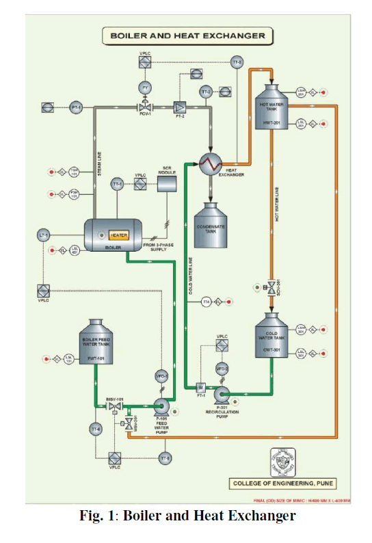 |
| Process Description: The boiler drum made up SS304 contains water which is electrically heated with a PWM controller and generates steam at 4 bar and 144 ºC. The water for heating is pumped from a boiler feed water tank using a positive displacement pump. The steam generated flows towards the heat exchanger through an equal percentage globe valve which controls the steam flow. |
| The heat exchanger being of tubular counter flow type, water to be heated is pumped from a cold water tank from the other end using a centrifugal pump. The condensate formed in the heat exchanger during heat transfer is collected in a separate condensate tank. The hot water is collected in hot water tank which also be either mixed in the cold water tank or can be added partially/fully to the feed to the boiler to change the feed water temperature. |
| Variables Measured: Following process variables are measured: |
| 1) Level of water in the boiler drums (LT-1) |
| 2) Drum pressure (PT-1) |
| 3) Steam temperature (TT-1) |
| 4) Boiler feed water temperature (TT-5) |
| 5) Boiler feed water flow ((FT-2) |
| 6) Temperature from water from hot water tank for mixing with boiler feed water (TT-4) |
| 7) Steam flow (FT-3) |
| 8) Heat exchanger steam inlet temperature (TT-2) |
| 9) Heat exchanger water inlet temperature (TT-4) |
| 10) Heat exchanger water outlet temperature (TT-3) |
| 11) Heat exchanger water flow (FT-1) |
III. EXPERIMENTATION AND MATHEMATICAL MODELLING |
| There are three controlling loops in this set-up which are as follows: |
| ïÃâ÷ Boiler Level Loop |
| ïÃâ÷ Boiler Temperature Loop |
| ïÃâ÷ Heat Exchanger Outlet Temperature Loop |
| At the time of experimentation boiler is maintained at steady state such that input steam flow to the heat exchanger will be at constant and inlet water flow to the heat exchanger is also at constant speed. Level loop and temperature loop of boiler are considered as disturbances to the system and they are maintained at steady state i.e. temperature, level and pressure of boiler is at constant rate. To achieve this condition level and temperature loops of boiler are operated in closed loops and temperature loop of heat exchanger is operated in open loop and the response is observed to obtain mathematical model by System Identification and also for controller designing. |
| Heat exchanger’s temperature loop is shown below: |
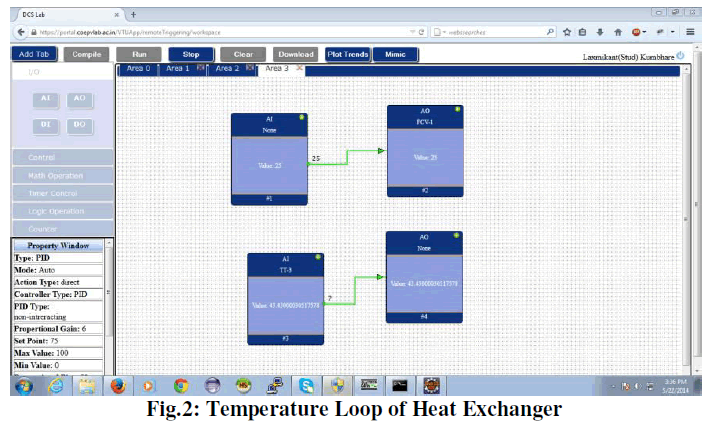 |
| In this loop inlet water flow (FT-1) to the heat exchanger is kept constant and temperature (TT-1), pressure (PT-1) and level (LT-1) of boiler is kept at steady state condition. A step change is given to the inlet steam flow to heat exchanger (FCV-1) and temperature (TT-3) of heat exchanger is observed. |
| System Identification: From experimentation the data is acquired which is used for System Identification to obtain mathematical model. The System Identification procedure is as follows: |
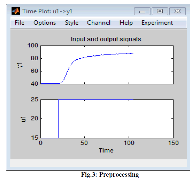
| Plotting and Pre-processing: It involves importing input/output data from experimentation with respect to time. Trends are removed from imported data as a part of pre-processing. Pre-processing improves data quality by removing unwanted data from imported data. Pre-processing involves filtering, selecting range, de-trending, removing means etc. |
 |
| Estimation and Validation of Transfer Function Model: A transfer function model is given as: |
| Transfer Function= (0.2304s + 0.01265)/(s2 + 0.06689s + 0.005244) |
| PID controller is designed for this transfer function model |
IV. PID CONTROLLER DESIGNING |
| PID Controller: PID controllers considered as a good control techniques used now days in industrial applications due to their simplicity and robustness. Moreover they are available at little costs. |
| The Proportional-plus-Integral-plus-Derivative (PID) controllers have found wide acceptance and applications in the industries for the past few decades. It has a simple control structure which was understood by plant operators and which they found relatively easy to tune. In spite of the simple structures, PID controllers are proven to be sufficient for many practical control problems and hence are particularly appealing to practicing engineers. An abundant amount of research work has been reported in the past on the tuning of PID controllers.PID means Proportional-Integral- Derivative, referring to the three terms operating on the error signal to produce a control signal. Since many control systems using PID control have proved satisfactory, it still has a wide range of applications in industrial control. |
| Process Reaction Curve Method: This method remains a popular technique for tuning controllers that use proportional, integral, and derivative actions. The Zeigler Nichols Open-Loop Tuning Method is a way of relating the process parameters - delay time, process gain and time constant - to the controller parameters - controller gain and reset time. It has been developed for use on delay-followed-by-first-order-lag processes but can also be adapted to real processes. |
Open Loop (Feed Forward Loop) |
| ïÃâ÷ Make an open loop step test |
| ïÃâ÷ From the process reaction curve determine the transportation lag or dead time, the time constant or time for the response to change, and the ultimate value that the response reaches at steady-state. |
| ïÃâ÷ Determine the loop tuning constants. Plug in the reaction rate and lag time values to the Ziegler-Nichols openloop tuning equations for the appropriate controller P, PI, or PID to calculate the controller constants. Use the table below |
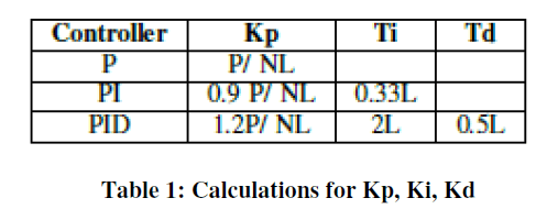 |
| Where, |
| P= Percent change of input |
| N= Percent change of output / tau |
| L= tau (dead) |
| R= tau (dead) /tau |
| And calculations are done by using following equations: |
| P = Change in Process Variable/ Change in Manipulated Variable |
| N = K (Change in Manipulated Variable) / tau |
| R = L / tau |
Calculations: |
| P= (87.42- 40.3)/ (25-15) = 4.712 |
| Time delay = 30 seconds |
| Tau = 720 seconds |
 |
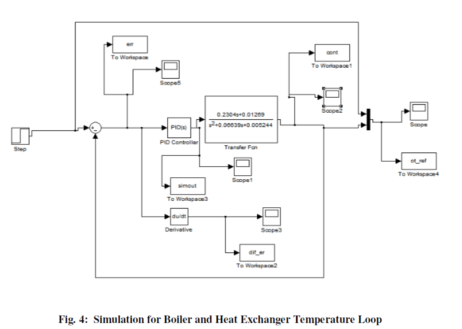
| Transfer function model is obtained from system Identification and PID controller design is done by controller parameters obtained from process reaction curve. The simulation diagram for boiler and heat exchanger temperature loop is given as follows: |
 |
V. RESULT AND DISCUSSION |
| This controller response is compared with step change to the input and the response is observed. The observed controller response is shown below: |
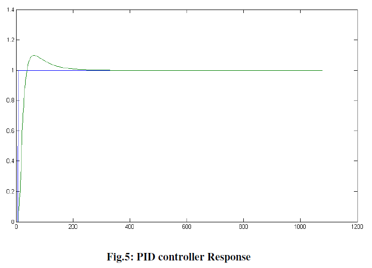 |
| In the fig 10, it shows the graph of time Vs amplitude of controller. |
| The controller characteristics are given in table shown below: |
 |
VI.CONCLUSION |
| Mathematical modeling of Boiler and heat exchanger set-up is done by System Identification method. System Identification method is better option to predict mathematical model of a complex system as well as it takes much less time to estimate a model than first principle method. |
| From the controllers response graph it is observed that with slight delay and overshoots the controller follows the model with less oscillations and the response is very fast. |
References |
|