ISSN ONLINE(2278-8875) PRINT (2320-3765)
ISSN ONLINE(2278-8875) PRINT (2320-3765)
Jonathan U. Agber
|
| Related article at Pubmed, Scholar Google |
Visit for more related articles at International Journal of Advanced Research in Electrical, Electronics and Instrumentation Engineering
Hybrid stepping motors can be analyzed as synchronous motors with constant field excitation. One limitation on the operation of these motors is the inability to regulate the permanent magnet (PM) mmf in order to obtain a family of steady state characteristics like conventional synchronous motors. The aim of this paper is to investigate the dependence of the PM hybrid motor characteristics on rotor excitation. Hence the design and construction of a wound-rotor motor, in which the two permanent magnets in the rotor of the hybrid stepping motor were replaced with wound soft iron formers. Static tests with varying rotor mmf were carried out and the results obtained show that the holding torque varies with rotor excitation and also that the PM mmf varies with the stator excitation.
Keywords |
| Stepping motor, hybrid stepping motor, wound-rotor motor, synchronous motor, steady-state characteristics. |
INTRODUCTION |
| The relationship between the hybrid stepping motors and synchronous motors had been established [1], [2], [3], [4], [9], [10]. This makes it possible to use synchronous motor theories for the investigation of stepping motor characteristics [6].One limitation on the operation of these motors is the inability to control the permanent magnet (PM) mmf in order to obtain a family of steady state characteristics like conventional synchronous motors. As the demand for variable speed drives is on the increase in recent years and stepping motors have shown to yield a competitive fully-controllable variable-speed system [8], interest to make it fully compatible with the conventional synchronous motor has also risen.This had led to the design and construction of a hybrid stepping motor with a ring coil [7], in which the stator laminations were divided into two sections and separated by a ring coil and the PM in the rotor was replaced by a soft iron sleeve. The construction of a wound-rotor (WR) motor involved the replacement of the two permanent magnets in the rotor of the PM hybrid stepping motor with wound soft iron formers. The design method used was developed at the University of Newcastle Upon Tyne and documented [3], [6], [7].The basis for the design was the PM hybrid stepping motor model VM156-270BK manufactured by GEC. |
| The motive behind the construction of the WR hybrid motor was to investigate the dependence of hybrid motor performance characteristics on the variation of rotor mmf and the possibility of obtaining similar characteristics as those displayed by the synchronous motor. Hence the WR motor underwent tests covering a sufficiently wide operating range. The voltage was sine wave and the range covered was 115V/10A, 230V/7.5A and 440V/5A. |
| Tests were carried out using115V/10A at selected step frequencies using the following rotor mmfs: 360, 480, 600 and 840At. |
| This paper presents the test results of the PM and WR hybrid stepping motor. The test results show that if there is a means of varying the rotor mmf of a PM hybrid stepping motor, it is capable of producing steady state characteristics similar to those of the conventional synchronous motor. |
II. INSTRUMENTATION |
| The block diagram of the experimental rig is shown in Figure 1. It consists of a stepping motor coupled to a hysteresis brake with a torque meter. The phase windings are connected to a power amplifier, which is connected to a signal generator capable of producing any wave form stored in the EPROMS that are mounted on the front panel. The voltmeter terminals of a wide band electronic wattmeter are connected across each phase winding, while a shunt is connected on the negative rail of each phase. The negative rail was used for the shunt, because one of the wires (screen)is earthed with respect to electronic wattmeter. The electronic wattmeter measured phase current, voltage, power and power factor. A change-over switch, which connects the motor cables to the power amplifier and a dc supply, was provided in each phase to ease measurement of the phase winding resistance at start and end of each test run. |
 |
III. CHOICE OF TEST VOLTAGES |
| The motive behind the construction of the WR hybrid stepping motor was to investigate the dependence of hybrid motor performance characteristics on the variation of rotor mmf. Hence a set of four suitable voltage combinations was chosen to cover a sufficiently wide operating range. Those selected were 115V/10A, 170V/7.5A, 230V/7.5A and 440V/5A. The voltage waveform was both sinusoidal and square. |
| The selection of test voltages was influenced by the fact that the output transformer of the 4-phase power amplifier has 115V/10A, 230V/7.5A and 440/5A tappings and the need to maximize the voltage-current product with a reasonable reserve factor. These rms values were used for both sine and square wave supplies. 170V/7.5A was chosen, because the data supplied by the manufacturer of the PM hybrid stepping motor was obtained using a test voltage of 230V and 170V corresponds to a peak of 240V, while 7.5A corresponds to a peak current of 10A. |
| The test voltage was sine wave with an rms value of 115V. Tests were carried out at selected step frequencies using the following rotor mmfs: 360, 480, 600 and 840At. |
IV. TEST PROCEDURE |
| Three test methods were adopted. At lower speeds, the phase currents were set at the limiting value and maintained by varying the applied voltage. At mid-range speeds, the phase voltage was set and maintained until the desired current limit was reached. At this point, the current was maintained until pull-out. At higher speeds, the voltage limit was set and maintained throughout the test. Using these procedures, the tests described below were carried out. |
A. Pull-out tests |
| During the pull-out tests at lower speeds, once the test speed had been reached and the current limit established, the torque was increased slowly and the current maintained by reducing the signal generator gain. When the pull-out torque was attained, the rise in current was so swift that it became impossible to control. The motor lost synchronism and pulled out. |
| At midrange frequencies, the voltage limit was set and as the torque was increased, the current rose until it reached the set limit. This current was then maintained until the motor pulled out. |
| At higher step frequencies, the applied voltage was set to the limiting value and the torque was applied. When the torque was increased, regulation caused the voltage to fall and the signal generator gain was adjusted to keep the voltage constant. As the pull-out torque approached, the voltage fell rapidly making accurate adjustment difficult and eventually the motor pulled out. Only the speeds and values of torque at which pull-out occurred were recorded. |
B. Full load and variable load tests |
| Full load was taken as seventy percent (70%) of the pull-out torque. The tests were carried out in the same manner as for pull-out. The only difference was that some mid-range step frequencies which were currentlimited during pull-out, became voltage limited at full load. This was because the voltage limit was set at no load. As the torque was gradually increased, the voltage fell as the current rose. As the value of the full load torque is less than the pull-out, it happened that the value of full load torque was reached before the current reached its limiting value. The following were recorded:- speed, torque, phase voltage, currents and powers. |
| Variable load tests were carried out at selected speeds. At 170V/7.5A, 2667 steps/sec (800 rpm) was chosen because it gave the maximum output power. The step frequencies that were chosen for the PM hybrid motor include 1000, 2000, 2667, 3333, 4000, 5000, 8333, 10000, and 11666 steps/sec at 115, 230 and 440V respectively. |
| Variable load tests were carried out on the WR hybrid motor to enable a comparison to be made with the PM hybrid motor. The tests covered step frequencies between 1000 and 4000 steps/sec at various rotor mmfs. The following were recorded during these tests: phase voltages, currents, powers and torque and the rotor current and power were also recorded. |
V. PRESENTATION OF TEST RESULTS |
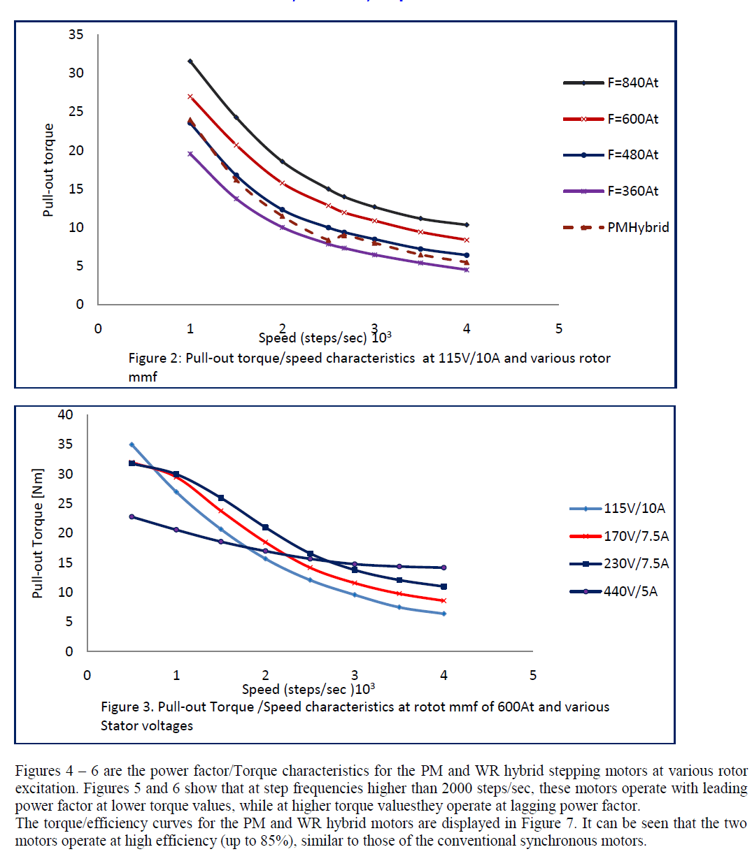
| The test results are presented in graphical form. Figure 2 is the pull-out torque vs speed characteristics at 115V/10A limit for the PM and WR hybrid motors. The PM hybrid rotor is excited at the PM rated mmf, while the WR hybrid rotor is set at 360At, 480At, 600At and 840At. |
| Figure 2 shows that a family of pull-out torque/speed characteristics can be produced by keeping the stator voltage constant and varying the rotor excitation. For the PM hybrid stepping motor, since the PM flux cannot be varied, only one curve is displayed. |
| The pull-out torque vs speed characteristics for variable stator voltage at rotor excitation of 600At is shown in Figure 3. This figure shows that at fixed rotor excitation, the stator voltage can be varied to produce a family of steady state characteristics for both the PM and WR hybrid stepping motors. For convenience, only the characteristics for the WR hybrid motor are shown, since the two motors display similar characteristics, except for the torque dips exhibited by the PM hybrid stepping motor at some step frequencies. |
 |
 |
VI. DISCUSSION OF RESULTS |
| These tests were carried out between 1000 and 4000 steps/sec, with constant or varying rotor mmf. Tests with varying rotor excitation showed that the pull-out torque increases with increase in the rotor excitation, which is an interesting feature. The pull-out torque vs speed characteristics at various rotor mmf are displayed in Figure 2. It can be seen that the performance range of this motor improves with the increase in rotor mmf. The torque dips that appeared in the PM hybrid steppingmotor pull-out torque curves were not encountered. |
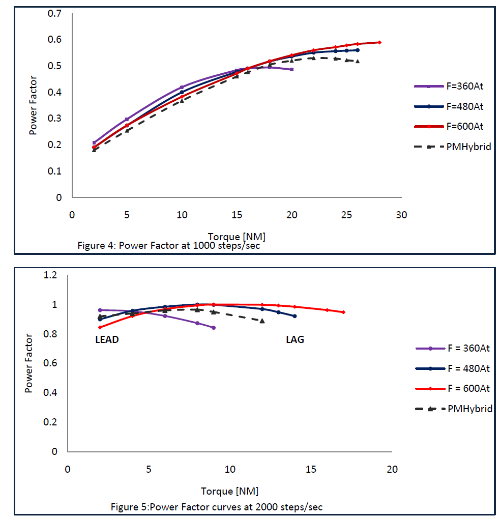
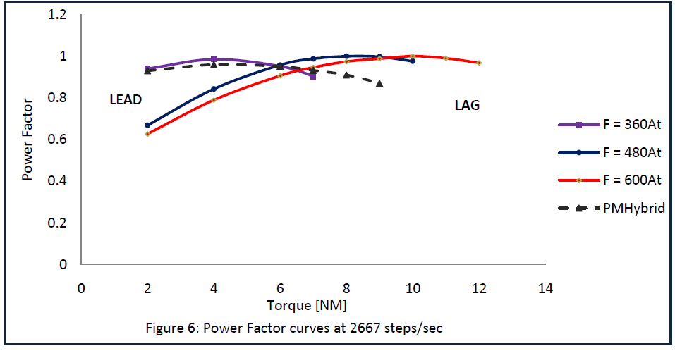
| Variable load tests were carried out at selected speeds with constant terminal voltage. The rotor mmf used for these tests were 360, 480, 600 and 840At. The power factor curves are shown in Figures 4, 5 and 6. It can be seen that with well controlled rotor mmf, the WR hybrid motor can operate at very high values of power factor and efficiency. In fact with suitable control, it is possible to maintain a constant power factor at fixed speed with varying load torque. The similarities in behavior with synchronous machines are striking. |
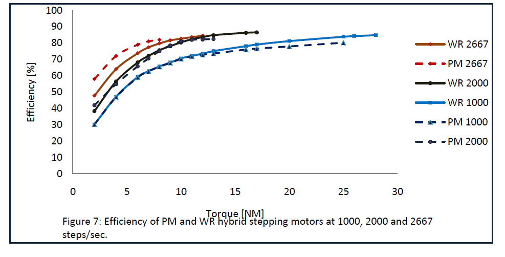
| The efficiency curves shown in Figure 7 also show that this motor can maintain high efficiencies at high torque values. Efficiency values of 85% were obtained throughout the speed range covered. |
| Other tests results confirm the resemblance of the WR hybrid stepping motors to orthodox synchronous motors, including the ability to work with lagging and leading power factors. |
VII. COMPARISON OF THE WR AND PM STEPPING MOTORS |
| The comparison of WR and the PM hybrid motors will be based on the performance characteristics of the two motors, i.e. measured pull-out torque, efficiency and power factor. |
A. Pull-out torque characteristics |
| In Figure2, the pull-out torque vs speed curves for the two motors operating at 115V rms, sine wave supply are presented. It can be seen that pull-out torque curve obtained from the PM hybrid motor liesbetween those of the WR stepping motor measured at rotor mmf of 360 and 480At. |
| The absence of torque dips in the WR hybrid curves shows an improvement in the dynamic characteristics. This may be due to the changed rotor flux, since this affects the damping and consequently the resonance properties (stability) of the motor. |
 |
 |
| Tests at varying rotor mmf show that it is possible to obtain a family of pull-out torque vs speed curves by just varying the rotor excitation as is done with synchronous motors. |
| Figure 3 contains the pull-out torque/speed characteristics for the WR hybrid stepping motor at various stator voltages. The characteristics for the PM hybrid motor are not shown, because they are similar to those of the WR motor, except that they display torque dips at certain frequencies. The absence of torque dips makes the WR hybrid stepping motor more stable than its PM counterpart. |
B. Power factor and efficiency curves |
| The power factor curves of the two motors obtained at 1000 steps/sec are displayed in Figure 4, while the efficiency curves are in Figure 7. The power factor of the WR hybrid motor is superior to those of the PM hybrid motor at lower frequencies, while at higher frequencies, however, the PM hybrid motor performance curves are superior to the WR. This discrepancy in the efficiency is probably due to the increased magnetic and mechanical losses in the WR hybrid motor. The difference in power factor may be connected with the dependence of the PM mmf on the stator excitation. The measured power factor and efficiency curves for this condition are displayed in Figures 6 and 7. The ability to operate with leading and lagging power factors makes them comparable with synchronous motors. |
CONCLUSION |
| This paper has dealt extensively with the steady state tests of the PM and WR hybrid stepping motors. Various important steady state characteristics have been covered. |
| A parametric variation is provided for the WR hybrid stepping motor in order to highlight some critical features associated with the dependence of the motor performance on rotor mmf. This has been taken with a view to improve the design and operating range of the PM hybrid stepping motors. The performance curves of the WR motor showed not only an improvement in stability, but also that the performance of the PM hybrid motor can be further improved if more powerful magnets are used in the rotor. |
References |
|