Keywords
|
| sbRIO, stepper motor, LabVIEW (motion and vision) |
INTRODUCTION
|
| The purpose of this paper is to develop a real-time object tracking system which is robust against such disturbing situations like illumination variation, object shape deformation, and partial occlusion of target images. By employing the coordinate difference algorithm, the system has been made robust against illumination variation and small variation in object shapes. In order to achieve real-time performance in tracking, a VLSI hardware-implementation friendly algorithm has been developed. |
| Multiple co ordinate regeneration, a statistical method, has been developed to realize the tracking function, and online learning is adopted to enhance the tracking performance. Due to the hardware-implementation friendliness of the algorithm, an object tracking system has been built very efficiently on an sbRIO to realize a real-time tracking capability. At the working frequency of 60 MHz, the main processing circuit can complete the processing of one frame of image (640x480 pixels) in 0.1 ms in the high-speed mode and 0.8 ms in the high-accuracy mode. The experimental results demonstrate that this system can deal with various complex situations; including scene illumination changes, object deformation, and partial occlusion. Based on the system built on the sbRIO, we discuss the issue of VLSI chip implementation of the algorithm and self initialization of the system, i.e. the autonomous localization of the tracking object in the initial frame. |
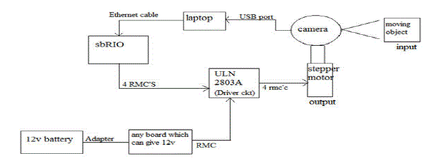
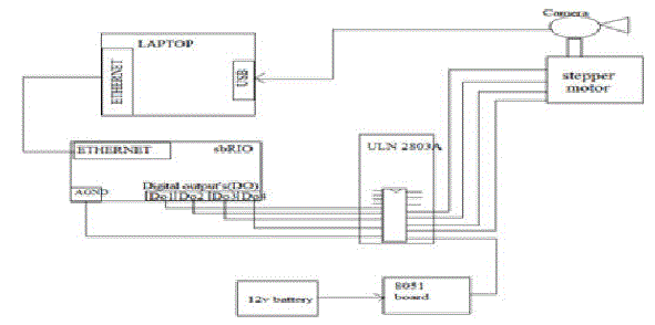
| Camera captures the image and sends it to the sbRIO. sbRIO takes the input image from camera and processes the image using the software logic explained in section IV and gives out the 4 digital output values to the stepper motor driver circui t. Driver circuit needs 12v voltage to trigger itself hence we give this voltage externally from the battery as shown in fig 1. Driver circuit now passes its 4 digital output's as 4 inputs to the stepper motor. Stepper motor thus now rotates in the respective direction in order to keep the object inside the frame. |
CO-ORDINATE DIFFERENCE ALGORITHM
|
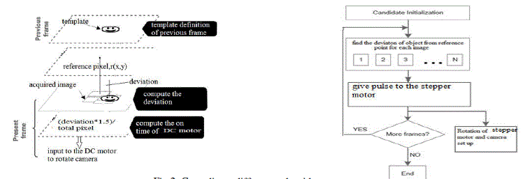
| In every consecutive frame , we find where exactly(coordinate value) is the template present using the pattern matching algorithm. Once this is found, subtract the present coordinate value with the reference coordinate value to find out the deviation of the template in every frame of video. Rotate the motor accordingly in either of the direction(whichever is necessary) until the template comes into the centre of the image. Deviation of template location up to +/- 10 is neglected since camera focuses the object or template even with this deviation as shown in fig 2. |
SOFTWARE IMPLEMENTATION
|
3.1 Steps Used for the Design of the System:
|
| • Software used is LabVIEW with 2012 version. |
| • Vision and motion, MAX are used under LabVIEW |
| • Camera captures the image (30fps, 176x144 image size.) and sends it to the laptop through USB port. laptop is included in the loop since the Logitech C110 is not compatible with sbRIO. |
| • We need to use NI camera which is compatible with sbRIO in order to make the project stand alone. Doing this has some restrictions |
| • Loaning NI camera is highly difficult |
| • Cost of the project increases |
| • sbRIO takes the input image from laptop through Ethernet cable and processes the image as follows: |
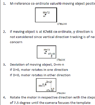
| • Let us assume image is of size 176x144. we have to find out the centre co ordinate value of the image and say it as reference point(88x72 in this case). |
| • This project is limited to only horizontal direction hence y co ordinate value is not of concern from now. |
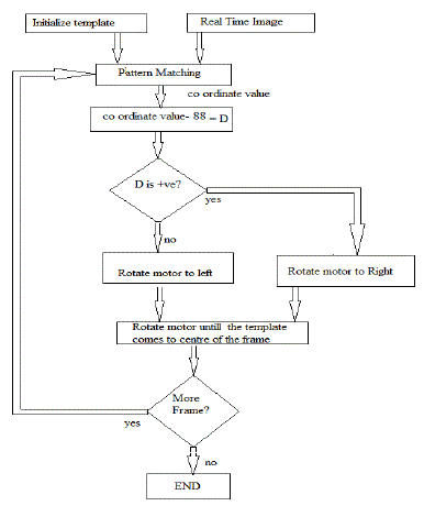
| • Once the sbRIO gets image from the laptop, it performs pattern matching as explained in the section 3.2.1. pattern matching gives the exact location of the template image in the main image. |
| • Once the location or co ordinate value of the template is found, sbRIO subtracts the present co ordinate value with the centre reference co ordinate value(88) to give the deviation. |
| • Deviation can be either positive or negative. |
| • if positive, motor rotates in one direction |
| • if negative, it rotates in opposite direction |
| • Rotate the motor to the corresponding direction continuously until the object comes inside the frame or it comes to centre of the real time image. |
| • Motor doesn't rotate for 2 situations |
| • object is in centre already |
| • pattern matching could not give the co ordinate value(object not found). |
| and gives out the 4 digital output values to the stepper motor driver circuit. |
| • Driver circuit needs 12v voltage to trigger itself hence we give this voltage externally from the battery. |
| • Driver circuit now passes its 4 digital output's as 4 inputs to the stepper motor. |
| • Stepper motor thus now rotates in the respective direction in order to keep the object inside the frame. |
HARDWARE IMPLEMENTATION:
|
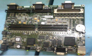
| In this paper, hardware is used National Instruments NI Single-Board RIO(fig 5) board-level embedded devices that provide a real-time processor, a Xilinx Spartan-6 FPGA (field-programmable gate array), analog and digital I/O, and built-in peripherals for custom embedded control and monitoring applications. The boards, according to NI, alleviate the effort of designing an entire embedded system from scratch, enabling designers to focus on the custom parts of their applications. |
4.1 HARDWARE SETUP
|
| 1. Connect sbRIO to laptop via Ethernet cable. |
| 2. Power on the sbRIO. |
| 3. Open MAX from desktop, find the sbRIO icon appearing under remote devices in MAX. |
| 4. Note down the IP address, gateway etc.. |
| 5. Find the "unconfigured device" in the last row of screen. |
| 6. Now go to network and sharing centre in the control panel- LAN- local area connection(double click)- pop up window occurs- open properties- double click on IP version 4(TCP/IP)- change the subnet mask, default gateway, preferred DNS server same as sbRIO. IP address should be like last integer must be different. |
| 7. Ensure that the softwares such as NI scan engine 4.0, NI serial RT 3.8.2 etc are installed. |
4.2 STEPS TO DOWNLOADLABVIEW CODE INTO sbRIO
|
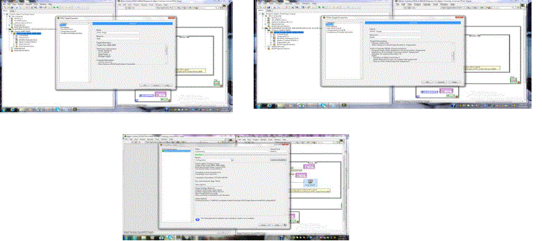
| 1. Now create FPGA project. right click on my computer in pop up window and add the VI |
| 2. Right click on project: untitled project1- new- target and devices- OK. |
| 3. Pop up window occurs, select RT sbRIO- double click- sbRIO is detected- OK. |
| 4. Discovers the device and it gets added to project explorer window. |
| 5. In chassis we find all the inputs and outputs of sbRIO. |
| 1. Drag and drop inputs and outputs into the block diagram of the VI. |
| 2. Connect inputs and outputs of sbRIO to that of the code. |
| 3. Run the VI. |
RESULTS
|
1. SIMULATION RESULTS
|
2. Verification of the Results:
|
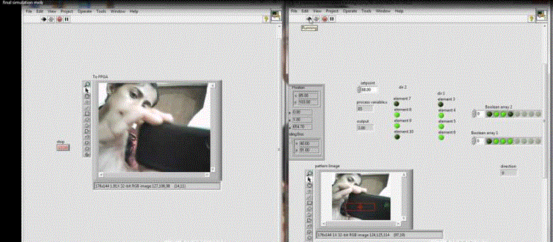
| In Fig 7, the object is found to be at 102 co ordinate value. when we subtract this value with reference point(88) we get -24, -ve sign indicates that motor has to rotate to its left and the 24 value gives to what extent the motor has to rotate. In Fig 8, the object is found to be at 85 co ordinate value. when we subtract this value with reference point(88) we get 3, +ve sign indicates that motor has to rotate to its right. since 3 pixels is not of that concern for this application, motor is kept still. In Fig 9, the object is found to be at 73 co ordinate value. when we subtract this value with reference point(88) we get 15, +ve sign indicates that motor has to rotate to its right and the 15 value gives to what extent the motor has to rotate. |
CONCLUSION
|
| A hardware-friendly tracking framework is established and implemented on sbRIO, thus verifying its compatibility with VLSI technology. Several problems that limit the hardware performance, such as complex computation, data transmission, cost of hardware resources, etc., are resolved. |
| Multiple co ordinate regeneration, a statistical method, has been developed to realize the tracking function, and online learning is adopted to enhance the tracking performance. Due to the hardware-implementation friendliness of the algorithm, an object tracking system has been built very efficiently on an sbRIO to realize a real-time tracking capability. |
| |
Figures at a glance
|
 |
 |
 |
 |
| Figure 1 |
Figure 2 |
Figure 3 |
Figure 4 |
 |
 |
 |
 |
| Figure 5 |
Figure 6 |
Figure 7 |
Figure 8 |
 |
 |
 |
 |
| Figure 9 |
Figure 10 |
Figure 11 |
Figure 12 |
|
| |
References
|
- S. Avidan, “Support vector tracking,” Pattern Analysis and Machine Intelligence, IEEE Transactions on, vol. 26, no. 8, pp. 1064 –1072, aug. 2004.
- N. Takahashi, K. Fujita, and T. Shibata, “A pixel-parallel self-similitude processing for multiple-resolution edge-filtering analog image sensors, ”Circuits and Systems I: Regular Papers, IEEE Transactions on, vol. 56, no. 11, pp. 2384 –2392, nov. 2009.
- A. Nakada, T. Shibata, M. Konda, T. Morimoto, and T. Ohmi, “A fully parallel vector-quantization processor for realtime motion-picture compression,” Solid-State Circuits, IEEE Journal of, vol. 34, no. 6, pp. 822 –830, jun 1999.
- B. Babenko, M.-H. Yang, and S. Belongie, “Robust object tracking with online multiple instance learning,” Pattern Analysis and Machine Intelligence, IEEE Transactions on, vol. 33, no. 8, pp. 1619 –1632, aug. 2011.
- " A Hierarchical Approach to Robust Background Subtraction using Color and Gradient Information" by Omar Javed, KhurramShafique and Mubarak ShahComputer Vision Lab,Schoolof Electrical Engineering and Computer Science,University of Central Florida
- " A Statistical Approach for Real-time RobustBackground Subtraction and Shadow Detection" byThanaratHorprasert David Harwood Larry S. Davisthanarat@cs.umd.edu harwood@umiacs.umd.edu lsd@umiacs.umd.edu Computer Vision LaboratoryUniversity of Maryland,College Park, MD 20742
- "Moving Object Detection in Spatial Domain using Background Removal Techniques - State-of-Art "ShireenY. Elhabian*, Khaled M. El-Sayed* and Sumaya H. Ahmed* Information Technology Department, Faculty of Computers andInformation, Cairo University, 5 Dr. Ahmed Zweel Street, Doki, Giza, 12613, Egypt
- " A Directional-Edge-Based Real-Time Object Tracking System Employing MultipleCandidate-Location
- Generation" Pushe Zhao, Hongbo Zhu, He Li, and Tadashi Shibata, Member, IEEE
|