ISSN ONLINE(2278-8875) PRINT (2320-3765)
ISSN ONLINE(2278-8875) PRINT (2320-3765)
H.Rahman1, B.H.Khan2
|
Visit for more related articles at International Journal of Advanced Research in Electrical, Electronics and Instrumentation Engineering
This research paper investigates the effects of line faults, line de-energization and line re-energization on the transient torsional stresses of steam turbine-generator (T-G) units in simultaneous AC-DC transmission system. The concept of damping the transient torsional torque stresses excited due to line faults by utilizing fast controllability and modulation of dc component in simultaneous AC-DC power transmission is also demonstrated. The studies are conducted on a simultaneous AC-DC line system which connects T-G set to a large ac system. For the purpose of comparison the simultaneous AC-DC power transmission system is replaced by an equivalent conventional AC system and performances are evaluated. The studies conclude that transient shaft stresses as a result of simultaneous AC-DC line fault and its subsequent switching events are significantly less severe than those of conventional AC line faults and subsequent switching. PSCAD/EMTDC software is used to carry out for simulation studies.
Keywords |
| PSCAD simulation, SSR, Simultaneous AC-DC Power Transmission, Transient Torsional Torque Stress. |
INTRODUCTION |
| SERIES capacitor compensation inAC transmission systems is an economical means to increase load carrying capability, control load sharing among parallel lines and enhance transient stability. However, capacitors in series with transmission lines may cause sub-synchronous resonance (SSR) that can lead to turbine-generator shaft failure and electrical instability at oscillation frequencies lower than the normal system frequency. Incidentally, the shaft damage can also occur due to fatigue when the peak torques exceeds a limit. HVDC systems are also extensively employed to increase the power transfer capability of the long distance transmission networks as well as to improve the stability of the transmission systems. In HVDC system, inverter operating at constant DC voltage and the rectifier operating at constant current is equivalent to constant DC power constant power operation which results in negative damping. The amount of negative damping is directly proportional to the DC power. The magnitude of interaction between rotor torsional vibrations and HVDC system greatly increases as converter firing angle increases in radial line without parallel AC link. Integral current controller causes series resonance at the sub synchronous frequency. Adding derivative feedback from DC current in integral current controller can introduce significantdamping. An alternate solution to the SSR problem is to modulate the converter delay angle in response to a control signal derived from the generator rotor velocity or the bus frequency [1, 6, 11, and 12]. |
| Previous works in reference [2-5] demonstrated an auxiliary damping controller (ADC) at the rectifier side of the HVDC link which could improve the modal damping of the turbine-generator system and thus allow higher levels of compensation ratio of the paralleled AC line. But, these controllers are difficult to simultaneously stabilize a power system operating at various loading conditions because they are designed at a particular operation point. The authors of this paper have earlier shown [7-9] that EHV ac line may be loaded to a very high level by simultaneous ac- dcpower transmission through it. The basic concept and proof justifying the feasibility of simultaneous ac-dc transmission has been reported in these papers. The improvement of transient stability by utilization of the inherent built-in short-term overload capacity of the dc system and rapidly modulating the dc power in case of simultaneous ac-dc line has been verified by the authors in paper reported earlier [10]. |
| As a result of large-signal electrical disturbances and their subsequent planned and/or unplanned switching incidents, theshaft segments of turbine-generator (T-G) units connected to HVAC/HVDC systems are subjected to transient torsional stresses. The phenomenon of transient torsional torques is also referred to as "torque amplification". Torsional stresses induce fatigue in the shaft material and reduce the shaft life-time. Fatigue phenomenon is a cumulative process and each shaft segment loses some of its life-time as a result of each torsional oscillations. The level of induced fatigue depends upon the amplitude of the imposed torsional stress [1]. |
| The objectives of this paper are: |
| (1)To investigate the phenomenon of transient torques in a simultaneous AC-DC Transmission system based on timedomain simulation studies. |
| (2)To compare the torsional impact of a simultaneous AC-DC transmission line fault and its subsequent blocking and releasing firing pulse to SCRs, and line CBs opening and reclosing with that of an equivalent fault on a HVAC system under similar conditions. |
| The paper is organized as follows; |
| Section 2 describes the control principle to reduce and damp transient torsional stresses excited due to disturbances in simultaneous AC-DC Transmission system. Two test systems, one conventional AC and one simultaneous AC-DC line, are introduced in section 3. Section 4 reports the result of digital time-domain simulation studies conducted on the test systems using the PSCAD/EMTDC program [14].A general discussion of the results is also provided in Section 4. The investigations conclude that simultaneous AC-DC line faults and their subsequent HVDC control reactions impose significantly, less severe transient torsional stresses on T-G shaft segments as compared to HVAC line faults and their subsequent switching incidents. |
CONTROL PRINCIPLE AND STRATEGY [10] |
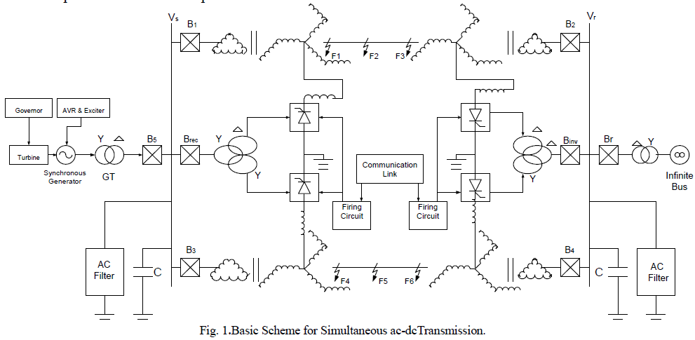
| The network in Fig. 1 shows the basic scheme for simultaneous ac-dc power flow through a double circuit ac transmission line. The dc power is obtained by converting a part of ac through line commutated 12-pulse rectifier bridge used in conventional HVDC and injected to the neutral point of the zig-zag connected secondary windings of sending end transformer. The same is reconverted to ac by the conventional line commutated inverter at the receiving end. The inverter bridge is connected to the neutral of zig-zag connected winding of the receiving end transformer. Each transmission line is connected between the zig-zag windings at both ends. The double circuit transmission line carries both 3-phase ac as well as dc power. |
 |
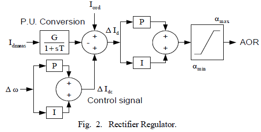
| HVDC links, under traditional controls, do not provide synchronizing or damping effects in response to disturbance on ac side. However, the controllability of an HVDC link is inherently fast and this can be used to regulate the power flow for system damping. |
 |
| Where, and are the actual and rated generator angular per unit speeds respectively. While the first term on the right hand side of equation (1) influences the transient behavior of the system, the second term influences the steady state. The control signal (ΔIdc) provides retarding energy to generator as well as damping to the system. |
 |
DESCRIPTION OF SYSTEM STUDIES |
| The network depicted in Fig. 1 is taken up for detailed studies using PSCAD/EMTDC. A T-G set of 2220 MVA, 24kV which is delivering power to an infinite bus via a double circuit ac transmission line. The T-G set is equivalent of three 740MVA, 24kV T-G set which are connected in parallel and are under equal loading conditions; thus they can be represented by a single equivalent T-G set. Fig. 3 shows the shaft system of the equivalent T-G set. The shaft system is composed of one high-pressure (HP) turbine, one intermediate pressure (IP) turbine, two low-pressure (LPA, LPB) turbines, generator rotor (G) and AC Machine exciter (EXC). The generator electrical system is represented in Park’s d-q-o frame and its mechanical system is represented by a mass-spring-dashpot system. Dynamics of the governor system of the T-G sets are neglected. The mechanical power supplied by turbine is assumed to remain constant corresponding to steady state operating condition. Dynamics of the excitation system of the T-G sets are included in the simulation model. The line considered is a three-phase, 400 KV, 50Hz, 450Km converted to simultaneous AC DC transmission line [9]. Each breaker (CB) is assumed to be an ideal switch. |
| Transmission lines are represented as Frequency Dependent (Phase) model. The Frequency Dependent (Phase) model is basically a distributed RLC traveling wave model, which incorporates the frequency dependence of all parameters. The converters on each end of dc link are modeled as two units of line commutated six-pulse bridge resulting into twelve-pulse output. The CIGRE Benchmark [13-14] modified to suit at dc voltage and current in the present case has been adopted for the control of converters. These include constant current (CC) and constant extinction angle (CEA) and voltage dependent current order limiters (VDCOL). The converters are supplied from ac bus through Y-Y and Y- converter transformers. Each bridge is a compact PSCAD representation of a DC converter, which includes a built in 6-pulse Graetz converter bridge (can be inverter or rectifier), an internal Phase Locked Oscillator (PLO), firing and valve blocking controls and firing angle ()/extinction angle () measurements. It also includes built in RC snubber circuits for each thyristor. AC filters at each end on ac sides of converter transformers are connected to filter out 11th and 13th harmonics. These filters and shunt capacitor supply reactive power requirements of the converters. |
 |
TRANSIENT STATE SIMULATION |
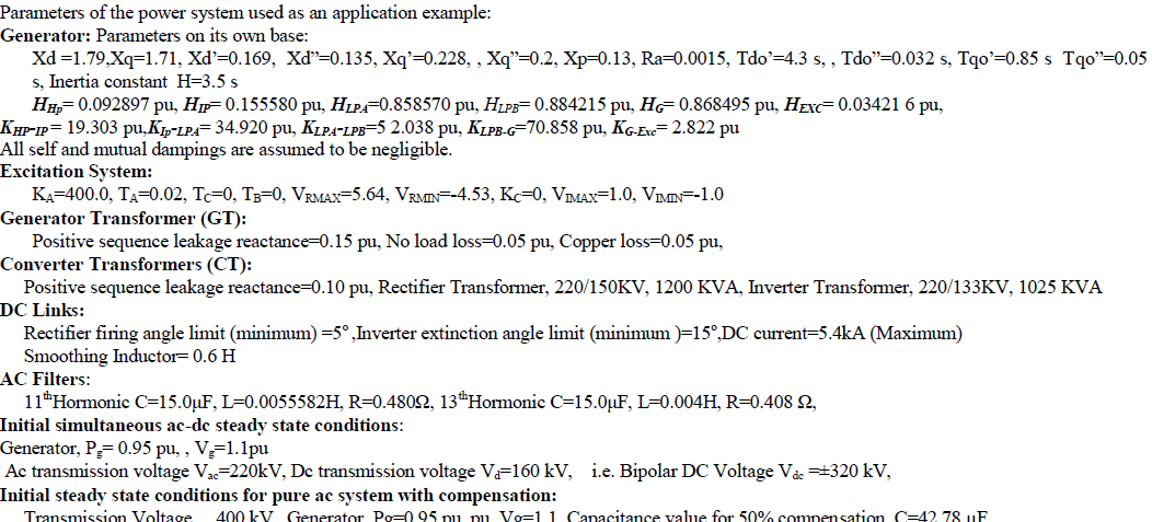
| A time domain simulation study is carried out to verify the effectiveness of proposed scheme in the environment of PSCAD/EMTDC. For the purpose of comparison, simulation study was repeated for the same line with conventional series capacitor compensated HVAC system. For both cases, the real power transfer through the transmission line is kept as same. Initially, the two schemes, namely, simultaneous AC-DC and conventional HVAC are operating in steady state conditions. The details of the operating conditions are mentioned in the Appendix. It has been confirmed through simulation studies, that simultaneous AC-DC transmission system with proposed control strategy of dc modulation effectively damps the system transient torsional torque oscillations. |
A. CONVENTIONAL AC TRANSMISSION WITH SERIES COMPENSATION |
| The practical series capacitive compensation does not usually exceeds 75% for a number of reasons, including load balancing with parallel path, high fault current, and the possible difficulties of power flow control. In systems where sub-synchronous resonance is main concern, the compensation is limited to 30% [4]. |
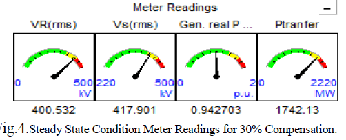
| For the purpose of comparative study, the same network as depicted in Fig. 1 is reduced to conventional HVAC by deleting the HVDC part and replacing zig-zag transformer with Δ-Y transformer along with addition of compensation. This HVAC system is operating in its steady state and delivering same real power to the receiving end as that in the case of simultaneous AC-DC system. The meter reading in Fig 4 depicts steady state pre fault condition of HVAC system with series capacitor compensation of 30%. |
 |
CASE (A1): FAULT NEAR SENDING END |
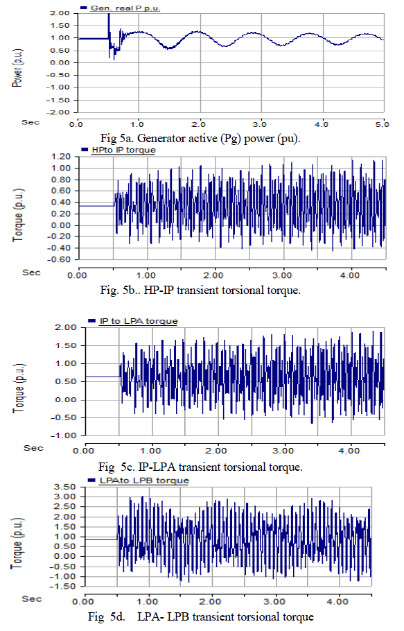
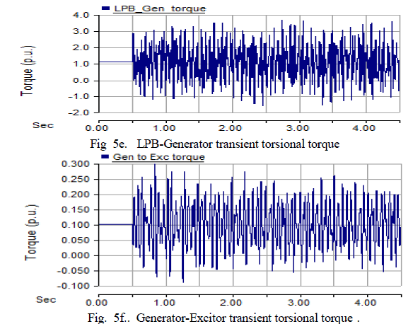
| The generator delivers 0.9427 p. u. pre-fault power to receiving end. At time t=0.5 sec a solid three-phase to ground fault occurs near sending end. The fault is detected and after a period of four cycles (80ms), trip signals are given simultaneously to circuit breakers B1and B2 at both ends of faulty line to clear the fault. Thereafter, CBs are successfully reclosed after a delay of five cycles (100ms) from the instant of clearing fault. Total disturbance duration 180ms. |
| Fig. 5 show the transient torsional torques responses when HVAC with 30% compensated system is subjected to a solid three-phase to ground fault at one of the line near sending end. |
 |
 |
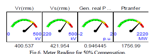
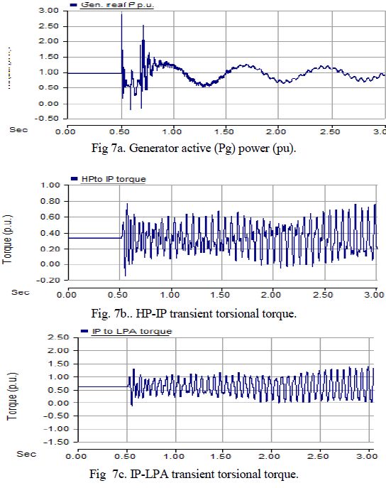
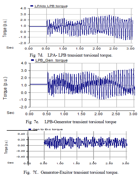
| A similar fault condition with the same sequence of events was created for pure HVAC line with 50% series compensation. The pre-fault power level is considered to be same as that for the above cases as indicated by meters reading in Fig.6. |
 |
| Fig. 7 show the transient torsional torques responses for this case. |
 |
 |
CASE (A2): FAULT NEAR RECEIVING END |
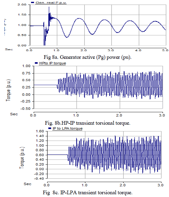
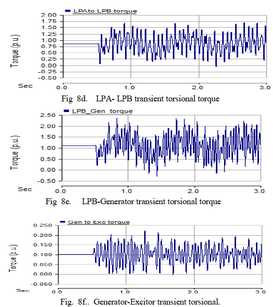
| Now consider a similar a solid three-phase to ground fault occurs with the same sequence of events near the receiving end for 50% compensated line. |
| Various transient torsional torques responses for this fault condition are shown in Fig. 8. |
 |
 |
B. SIMULTANEOUS AC-DC TRANSMISSION |
| The details of EHV ac line converted to simultaneous AC-DC line are given in Appendix. |
| The simulation study is carried for the following cases:q |
CASE (B1): FAULT NEAR SENDING END |
| Initially, the simultaneous AC-DC system is assumed to be operating in steady state, the meter readings for different variables are given in Fig.9. |
 |
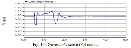
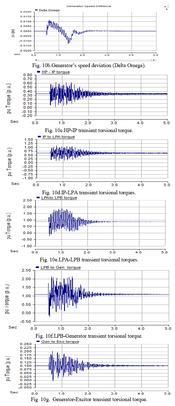
| The generator delivers 0.95 p. u. pre-fault power to receiving end. At time t=0.5 sec a solid three-phase to ground fault occurs near sending end F1 as shown in Fig. 1. The fault is followed by blocking of firing pulses to converter SCRs and activation of bypass valves. After a period of four cycles (80ms), trip signals are given simultaneously to circuit breakers B1and B2 at both ends of faulty line to clear the fault. Next, pulses to SCRs are released. Thereafter, CBs are reclosed after a delay of five cycles (100ms) from the instant of clearing fault. Fig. 10 shows the transient torsional torques responses of the generator for this fault condition. |
 |
 |
 |
CASE (B2): FAULT NEAR RECEIVING END |
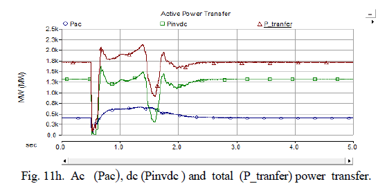
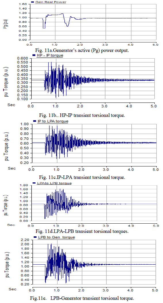
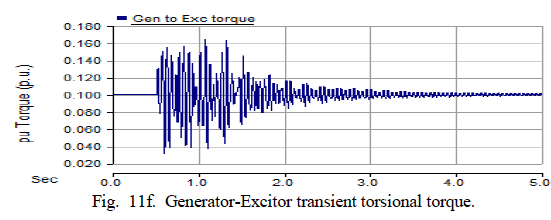
| Now considering a similar solid three-phase to ground fault with the same sequence of events near the receiving end F3 of the line (near inverter). Various transient torsional torques responses for this fault condition are shown in Fig. 11. |
 |
 |
DISCUSSION |
| Comparing the responses given in Fig. 10 and Fig. 11 for the case of sending end and receiving end faults following main observations are made: |
| The magnitude of speed deviation is almost same in both cases, but speed deviation recovers faster in case of fault at receiving end. |
| At the instant of the fault the generator power output is subjected to higher peak transient for sending end fault. |
| Transient torsional torques amplitudes arelittle bit higherin case of sending end fault. |
| After the clearance of the fault the real power oscillations have almost the same peak values for both fault locations. |
| The responses of dc voltage and current indicate no commutation failure for both fault conditions. |
| Thus the overall comparison of simulation results of Fig. 10 and Fig. 11 indicate that the fault at the sendingend excites the transient torsional torques of almost the same amplitudes as that at the receiving end. |
| Other type of faults such as single line to ground, double line to ground, double line and 3-phase faults were also studied near sending and receiving end. In all the above cases, thetransient torsional torques is found to be damped in duration, less than that for the solid three-phase to ground faults considered above. |
| Comparison of results between simultaneous AC-DC system and conventional HVAC system with series compensated system for the similar nature and duration of faults indicate: |
| The magnitude of generator speed deviation in case of simultaneous AC-DC system is more. However, this speed deviation reduces to zero at a faster rate in the simultaneous AC-DC system. |
| At the inception of fault, the generator real power overshoot is larger in case of pure ac system. The subsequent real power oscillation magnitude as well as duration is longer in pure ac system. While these oscillations decay much faster in case of simultaneous ac-dc system. |
| Comparison of Fig. 10 and Fig. 11 reveal that whenthe simultaneous AC-DC line faultoccurs at the receiving end, the maximum magnitudes of shafttransient torques are smaller. However, the differences are insignificant. On the contrary, comparison of Figs. 7and 8 shows that when the location of the ac line fault is at the sending end of the line, the maximum stress is imposed on the shaft segmentsare considerably higher than that when fault occurs at receiving end. The conventional ac system becomes oscillatory on occurance of fault. |
| Both conventional HVAC line fault and simultaneous AC-DC line fault inception excite transient torsional torques of the T-G set. Amplitudes of oscillations as a result of conventional ac line fault are significantly higher than those as a result of composite AC-DC line fault. |
| The HVAC line fault clearing and the composite AC-DC line de-energization by blocking the firing pulses to SCRs and opening of CBs do not have noticeable amplification impacts on the amplitudes of shaft transient torques imposed by fault inceptions. |
| Successful reclosure of the ac line results in dramaticincrease in the amplitudes of the shaft torques. On thecontrary, the simultaneous AC-DC line re-energizationby releasing of firing pulses to SCRs followed by CBs reclosure has a relatively smallimpact on the amplitudes of shaft torques. |
CONCLUSION |
| A novel approach to reduce and damp thetransient torsional torques amplitudes of the T-G set bysimultaneous AC-DC power transmission has been presented. A detailed study has been carried out in PSCAD/EMTDC environment to validate the proposed scheme. It has been demonstrated that the transient torsional torque stresses of the T-G set can be effectively damped bysimultaneous AC-DC power transmission with fast dc power modulation. |
| For the purpose of study, worst locations of faults (i.e. near the sending end, near inverter) and heavily loaded line (i.e. close to thermal limit) are considered. It has been demonstrated that effective control of dc component by simultaneous AC-DC power transmission considerably reduces and damps thetransient torsional torques amplitudes of the T-G set. Shaft transient stresses as a result of occurance of composite AC-DC line fault, fault clearing and autoreclosure are significantly less severe than those in conventional HVAC system under similar conditions. For the systems under investigation, the shaft transient stresses as a result of simultaneous AC-DC line fault and its subsequent switching process are not severe enough to reduce the shaft life-time. |
APPENDIX |
 |
References |
|