ISSN ONLINE(2278-8875) PRINT (2320-3765)
ISSN ONLINE(2278-8875) PRINT (2320-3765)
| Niranjan Ravi, Vishal Sundarrajan, Vetrivel DSB BE Student, Dept. of ECE, PSNA College of Engineering and Technology, Dindigul, Tamilnadu, India |
| Related article at Pubmed, Scholar Google |
Visit for more related articles at International Journal of Advanced Research in Electrical, Electronics and Instrumentation Engineering
In this paper, we have introduced a simple microstrip patch antenna in the Ultra Wideband (UWB) frequency range of 3-10.26 GHZ with a reduced return loss as low as -26 dB. The proposed antenna is simulated using ADS (Advanced Design System), an electronic design automation software for RF, microwave, and high speed digital applications and hardware fabrication of the same has been carried out. The simulation results shows the return loss of - 30 dB which is in accordance with the return loss of fabricated antenna. The results of hardware fabrication and software simulation are compared and the other simulation results such as power radiation, effective angle, directivity, gain are also found out in this paper.
Keywords |
| Microstrip, Ultra wideband (UWB), Return loss, ADS (Advanced Design System) |
INTRODUCTION |
| Ultra-wideband (UWB) radio is an emerging technology with some unique attractive features which are combined with researches in other fields such as wireless communications, radar, and medical engineering fields. Formally before 2001, UWB's application is limited mainly in military areas. However, since 2002, FCC(Federal Communications Commission) has gradually allowed the commercial usage of these bandwidths, which makes it possible that every common people could benefit the UWB features. Federal Communications Commission (FCC) regulate that the frequency for the UWB technique is from 3.1GHz to 10.6GHz in US. However, in Europe, the frequencies include two parts: from 3.4 GHz to 4.8 GHz and 6 GHz to 8.5 GHz. |
| The ultra-wideband (UWB) spectrum available for commercial applications has offered us an opportunity to achieve high-speed wireless communications and high-accuracy location applications. As one of key research areas in UWB technology, a lot of innovative broadband and miniaturization techniques for UWB antennas have been greatly invented and developed for years. [3]. In the existing paper, a compact design and construction of microstrip Ultra Wide Band (UWB) antenna is proposed. The proposed antenna has the capability of operating between 4.1 GHz to 10 GHz. The antenna parameter in frequency domain analysis have been investigated to show its capability as an effective radiating element. Furthermore, time domain Gaussian pulse excitation analysis in UWB systems is also demonstrated. [2]. A novel technique to increase the bandwidth of the conventional planar triangular monopole antenna (PTMA) is presented. With two symmetrical corrugations extended from the flat ground plane, a significant improvement on the impedance bandwidth up to 4:1 is achieved. [5]. Then, a new circular ultra-wideband fractal monopole antenna based on descartes circle theorem (DCT) with elliptical iterations is presented. The proposed fractal design is optimized for return loss of -15dB. Moreover, the proposed system has less weight and wind loading effect due to the fractal shape.SN khan 2008.The VSWR (Voltage Standing Wave Ratio) and radiation pattern proved that antenna is a good candidate for UWB applications. However, in the existing paper the return loss is about -15 dB. For better transmission, the return loss should be less than -14 dB. So, in this paper we have reduced the return loss further to -26 dB in simulation and was verified using the Network analyzer in the hardware fabrication. |
LITERATURE REVIEW |
| A compact ultra-wideband (UWB) monopole antenna with four band-notched characteristics is introduced in this paper. The proposed antenna can achieve four-band rejection at 3.4, 5.7, 8and 11 GHz with desired bandwidths only using one novel structure called nested complementary split-ring resonator (CSRR) which is etched inside the ground plane. This method used to obtain four- band notched characteristics is firstly proposed by [7]. The antenna has a small dimension of 35×27mm2. The VSWR and radiation patterns of the fabricated antenna are presented, which prove that the designed antenna is a good candidate for various UWB applications. |
PROPOSED ANTENNA CONFIGURATION |
| A. Design of Microstrip patch antenna: |
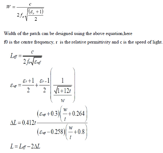
| The simplest patch antenna consists of a rectangular metallic patch on one side of a dielectric substrate and a ground plane on the other side of the dielectric substrate. The thickness of the metals of the patch and ground plane, t, is very small compared to the wavelength (t<< λ). However, the metal thickness, t, must be at least a few times larger than the skin depth. If the metal thickness is smaller than skin depth Ohmic losses in the patch and the ground plane drastically reduce the radiation efficiency of the antenna. Substrate thickness h, and its dielectric constant εr, play important roles in the radiation parameters of the antenna. Substrate thicknesses are usually in the range of 0.002λ0 < h < 0.1λ0, where λ0is the wavelength in free space. Substrate dielectric constants usually range from 2.2 <εr< 12. [4] |
| The basic length and width are given in the below equation. |
 |
| B. Dielectric Constant of the Substrate (εr): |
| The dielectric material that is used in the design of the Microstrip Patch Antenna is FR4 with εr= 4.4, as this one of the value of the dielectric substrate has been taken in order to reduce the size of the antenna. The frequency of operation for the patch is selected as 3 to 10.26 GHZ. Microstrip patch antenna has been designed in order to rule out the conventional antenna as the patch antennas are used in most of the compact devices. Therefore the height of the antenna has been decided as 1.6mm.A rectangular Patch antenna has been in the process of design; it is easy in the fabrication analysis and also in the prediction of the performance. The design of the antenna is being under process at 3-10.26 GHz frequency using the dielectric material with εr= 4.4 with a dielectric loss tangent (tan δ) = 0.019 with a height of 1.6 mm. |
| C. Feed point determination: |
| As there feed type has been specified and the parameters are calculated. The matching impedance is 50Ω. In order to have a matching of the impedance the connecter has to be placed at some distance from the edge which has a match of 50Ω. There is a trial and error method that has been adopted to check the minimum value of return loss. |
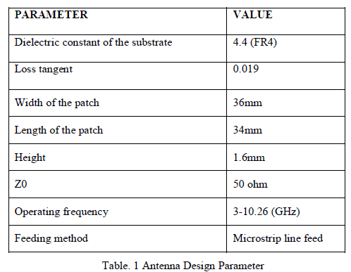 |
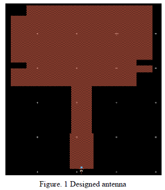
| The antenna is fabricated on FR4 epoxy substrate.The antenna with dimension of 34mm * 36mm (L * W) is fabricated on FR-4 epoxy dielectric with relative permittivity of 4.4. The designed antenna has the capability of operating between 3 GHz to 10.26 GHz with a 7.26 GHz bandwidth (fh-fl). |
 |
RESULTS AND DISCUSSIONS |
| A. Design of Microstrip patch antenna: |
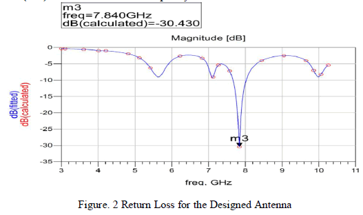
| Figure 2 illustrates the simulated and measured return loss against frequency of the antenna. Based on the simulated results, the antenna displays resonant frequencies at 7.840 GHz with S11 (return loss) of -30.430 dB. The antenna exhibits the return loss (S11) below -26 dB for the frequency mentioned. |
 |
| B. Antenna parameters: |
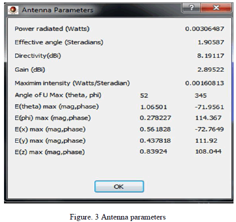
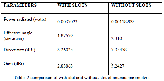
| The antenna parameters are obtained from the simulation software using ADS. The results for the designed antenna complies with the value of the existing microstrip patch antenna with the 80% reduction in gain. With the increased directivity in the UWB, the return loss is reduced and maximum output can be achieved. |
 |
 |
| C. Measured Results: |
| The figure below shows the Return Loss measured by Network Analyzer. |
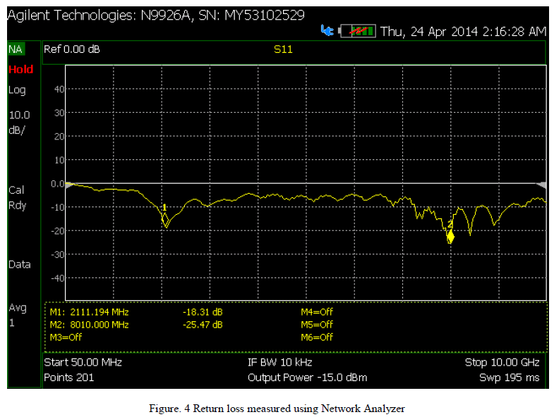 |
| The antenna for the following specifications is fabricated and verified for its return loss using network analyzer. The results show a good compliment with the simulation result and are tabulated below. |
 |
| Thus a comparison table is drawn from the following results |
 |
CONCLUSION |
| Thus from the above results it is evident that the return loss is greatly reduced for the following specifications. However, the focus is largely on increasing the Bandwidth in UWB frequency range, the paper provides a reduction in return loss to achieve maximum output. In order to increase the Bandwidth many slots have been introduced in the antenna. The future work will be extended by Array system. |
References |
|