ISSN ONLINE(2278-8875) PRINT (2320-3765)
ISSN ONLINE(2278-8875) PRINT (2320-3765)
P.Aravindan1, G.Subbulakshmi2
|
| Related article at Pubmed, Scholar Google |
Visit for more related articles at International Journal of Advanced Research in Electrical, Electronics and Instrumentation Engineering
Renewable energy is the most economic solution for new grid-connected capacity in areas with good resources. The RES power variation and their unpredictable nature may decrease the grids reliability. In this regard, this paper presents an enhanced control method for battery energy storage systems (BESS) to support the frequency of MG and with the ability of disconnecting from the MG to supplying in the island mode a local consumer. The combination of Battery Energy Storage Systems (BESS) with a hierarchical control of the resources provides a solution to overcome the frequency control issues within an MG. Within the BESS, a power electronics converter interfaces the energy storage unit with a single or three-phase MG. The power converters operation in two states, namely MG-tied or islanded, is an important feature to improve the MG flexibility and feasibility. The BESS may also provide voltage support in the point of common coupling with the MG. The proposed BESS may compensate the power absorbed by the local loads in order to improve the MG frequency response. When the MG power quality worsens under a certain stage, in terms of voltage and frequency, the BESS detaches from the MG and continues to operate islanded. The reconnection is accomplished a smoothly resynchronization of the local voltage with the MG, without troubling the local loads supply. In this proposed method, by proper maintenance of charging and discharging of battery, it enhances the lifetime of battery and it also provides the uninterrupted supply of load.
Keywords |
| Battery Energy Storage System (BESS), inverter, Microgrid (MG), Seamless transfer |
INTRODUCTION |
| The most important enterprise of the twenty-first century is the energy industry [9]. With the industrial growth, the demand for energy has increased. Within a matter of 10 years, for example, the peak electric power demand in India has grown from 30,000MW to 120,000MW[3].The energy demand in the form of oil for transport sector has also grown manifold. Out of the total energy demand, about 80% demand is met from the sources of fossil fuels [5]. Only 13.5% of the energy demand is met from renewable sources [2]. The break-up of share of various renewable sources is as follows: |
| Hydroelectric 2.5% |
| Nuclear 6.5% |
| Solar and Wind 1.5% |
| Biomass Balance |
| Renewable which can be renewed by nature again and again so that their supply is not adversely affected by the rate of their consumption are called renewable resources. The energy resources can be nuclear, fossil fuel, hydro, solar, biomass, wind, tidal, geothermal, ocean thermal and ocean tidal resources[1]-[5] .The solar energy is generally transformed into thermal or electric energy using solar devices[7]. The solar energy is, however, available during sunshine hours and the demand of thermal or electric energy may also exist during non-sunshine hours [3]. |
| The sun is a continuous fusion reactor in which hydrogen combines to form helium and liberates large amounts of heat in the process. The sun rays contain a large amount of energy in the form of electromagnetic radiation due to the continuous nuclear fusion reaction taking place in the sun. The energy is released at the rate of 3.7*1020 MW. This heat energy contained in the sun rays can be utilized to generate electric power. The current interest in energy storage is driven mainly by advances in storage technologies—the added benefits they bring through their implementation and more importantly, by the dramatic changes electricity markets are experiencing today [1] [2]. |
| Governments and electric utilities worldwide are implementing changes in their strategies and investments in an effort towards modernization of the grid. The impact of regulatory changes in the utility industry has been such that more attention is being focussed on environmental factors, asset utilization and customer energy management services— domains in which energy storage can have a positive and significant impact [3]. With an increased penetration of renewable resources like wind and solar, the industry is faced with new challenges brought about by the variable and intermittent nature of these sources. Recent advances and development in energy storage technologies suggest that storage may be a viable solution to these problems. Although energy storage systems (ESS) are expensive, large scale integration of renewable resources would be a difficult challenge without it [8]. |
| Complementing wind power with energy storage to solve issues pertaining to power quality, system reliability and protection have been studied in various cases [4]–[9]. Various other studies have also been completed in this area. Ribeiro et al. [1] discuss the integration of BESS into FACTS devices to form a more flexible and economic transmission controller capable of providing oscillation damping and voltage control. In [10] Xu et al. propose the use of an energy storage system connected to a variable speed wind turbine to achieve power oscillation damping. The objective is to better understand the control modes in order to determine the most appropriate ones for a given application; and to consider the role of storage in advanced applications, such as microgrids. This paper describes the BESS and gives a representation of the test results obtained during the commissioning and operation of the system. |
II.BATTERY LIFE TIME |
| Block diagram of BESS structure is shown in fig 1. |
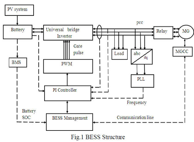 |
| Initially Battery is charged with the help of RES and Battery Management System is used for monitoring the charging and discharging level of the battery [2]. Therefore the battery life time can be expanded. By using three levels of universal bridge inverter, a power electronics converter interfaces the energy storage unit with a Microgrid and the communication line between the Microgrid Central Controller and Battery Energy Storage System management [3].The MGCC is also one of the monitoring blocks, which monitors the grid voltage and frequency. |
| the power generated by PV system is not sufficient to meet the local load means the load will import the power from the Microgrid and the battery is charged because the inverter act as converter. If the power generated is in excess, PV system export the power to the Microgrid. If the grid voltage is in abnormal condition, local load is disconnected from the Microgrid and it operates as island mode [8]. The synchronization process is very important [5]-[7]. So we are matching the inverter frequency with grid frequency using PI controller with PWM by varying the switching frequency and maintain the grid frequency. |
III.MODES OF OPERATION |
A. Introduction |
| There are two main categories of different modes of operation, they are: Stand alone or Off-grid mode and Grid tied or Grid connected ode. Stand-alone operation is a very important function of the MG to enhance the power supply reliability for the home users [10]. In this situation, PV is the only power generation, and the excess or deficient power is compensated by the battery. Because the outputs of the PV and the battery are limited, it is not allowed that all ac and dc loads are connected. Fortunately, most residential electric appliances are re-schedulable [6]. |
B. Stand Alone or Off-Grid Mode |
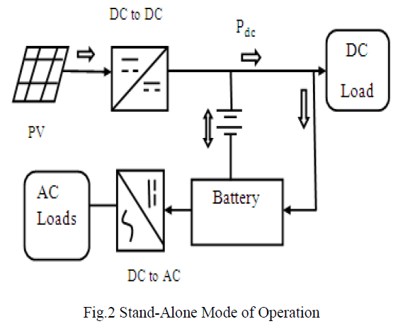 |
| The first category is shown in fig 2. In the stand-alone mode, the actual charging or discharging current of the battery depends passively on the PV supply and the on-site load demand since the battery directly connects to the load through the inverter [4]-[6]. To protect the battery against an excessive charge, the PV should be disconnected from the MG. On the other hand, In case of unavailability of RES to protect the battery against excessive discharge, the loads should be automatically connected to the Grid. |
C. Grid Tied or Grid Connected Mode |
| The second category is the situation where the load is connected to the utility grid. This is called âÃâ¬Ãâ¢Grid-tiedâÃâ¬Ãâ or âÃâ¬Ãâ¢GridconnectedâÃâ¬Ãâ mode. In this situation, both the PV and the Microgrid are power sources [6]-[8]. The main function of the PV is to generate power and provide local power support. And the excess or deficient power of PV is compensated by the Microgrid. If the PV output is more than the demand of the load and battery, the excess power will be transferred to the Microgrid [4]. |
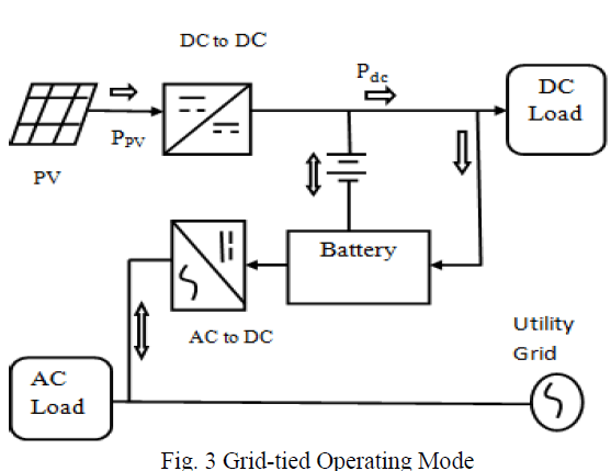 |
| Whether connecting the load to the Microgrid really depends on the condition of the MicroGrid .If the MicroGrid is in normal operation, the load will be connected to it. Once there is a failure in the MicroGrid, the load must be smoothly transferred to the stand-alone mode as soon as possible [2]. |
| In general, the operating states of the modules are determined by the power differences between the PV productions plus battery output (SOC).SOC current value is greater than the set value means island mode.SOC current value is less than the set value means Grid mode[3]-[7]. The transitions between different operation modes are shown in fig 3. |
IV.REQUIREMENTS OF PWM TECHNIQUE |
| The PI controller with PWM technique is mainly used for synchronizing the source frequency matching with the load frequency. |
A. PWM Technique |
| Using this controller circuit, this provides the output voltages for controlling the VSC Bridge by means of the pulsewidth modulation generator is shown in fig 4. Output voltage of the inverter needs to be varied as per load requirement [2]. Whenever the input DC varies, the output voltage can change .The most efficient method of doing this is by pulsewidth modulation control used within an inverter [8]. In this process, a fixed dc input voltage is given to the inverter and a controlled ac output voltage is obtained by adjusting the on and off periods of the inverter components [10]. This is the most accepted method of controlling the output voltage and this method is termed as Pulse-Width Modulation (PWM) Control [7]. |
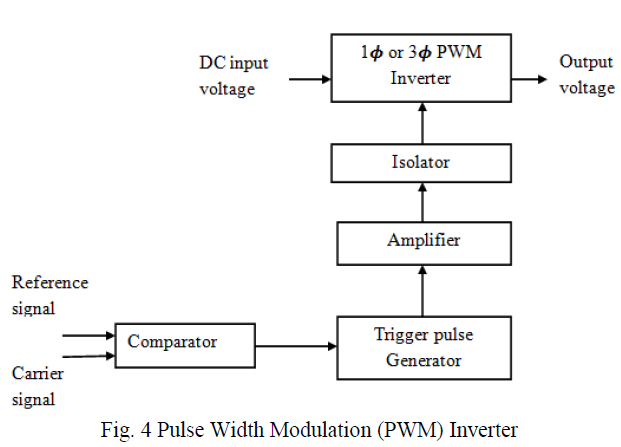 |
| It consists of power circuit and gate triggering circuit. The power circuit may be single phase or three phase inverter. The comparator compares reference signal and carrier signal [2]. The output is given to triggering unit. It gives pulses for the inverter. These pulses fed to the inverter through amplifier and isolator. Inverter output voltage can be controlled by varying the pulses of on and off time of the devices. The advantages possessed by PWM techniques are as under: The output voltage control with this method can be obtained without any additional components [6]-[7]. |
| ïÃâ÷ With the method, lower order harmonics can be eliminated or minimized along with its output voltage control. Its harmonics characteristics are improved. The switching losses also reduced. |
| ïÃâ÷ The capability of forming sinusoidal currents is provided by the introduction of the sophisticated technique called Pulse-Width Modulation (PWM). This technique provides the sequences of width-modulated pulses to control power switches. |
V.RESULT AND DISCUSSION |
| An enhanced control method for Battery Energy Storage Systems (BESS) to support the frequency of MG and with the ability of disconnecting from the MG to supplying in the island mode a local consumer. The PI controller with PWM technique is mainly used for synchronizing the source frequency matching with the Grid frequency and also used in the reduction of harmonics to attain the voltage stability. |
A. Transfer from Grid Mode to Island Mode |
| The transition between G-mode to I-mode is shown in fig 5.If any of the PCC voltage or frequency changes outside certain limits (indicating the worsening of PCC power quality), the BESS can switch to island mode in order to protect the local load. |
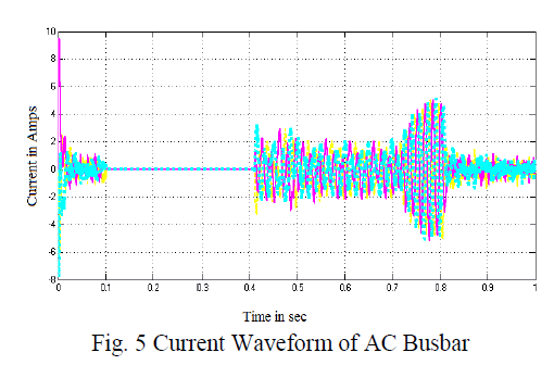 |
| The reconnection to the grid is accomplished after synchronization of the local voltage with the grid voltage without interrupting the local load supply. |
A. Voltage Waveform Of Universal Bridge Switching Device |
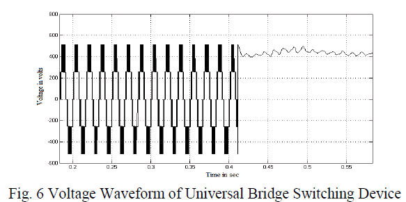
| The output voltage waveform of universal bridge is shown in fig 6. |
 |
B. State of Charge of Battery |
| The output waveform of SOC of Batteryis shown in fig 7. |
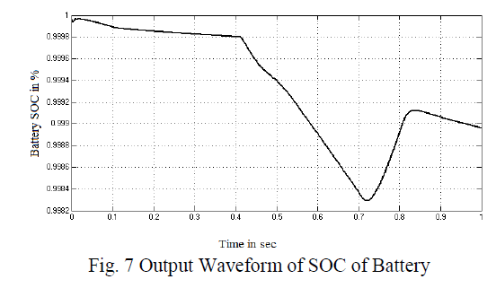 |
| The battery SOC is shown in fig 8. Initially the battery is charging with the help of RES. This indicates the full charging level. After that the battery is delivering the power to the local load, this represents the discharging level. With the unavailability of RES, the battery is again charging with the help of Grid source. |
CONCLUSION |
| This paper presented a BESS mainly designed to provide frequency support in MG, but having special control features. The BESS can operate both connected to the MG (G-mode) or in (I-mode), whereas the transition between the two states is seamlessly coordinated by an original control method. The BESS may serve local sensitive consumers connected on the local bus, by including special control functions to protect them in adverse MG operating conditions. Moreover, by partially or totally compensating the local loads, the MG is relieved by the corresponding power disturbance produced by their stochastic operation and thus the MG frequency deviation can be diminished. The transition between G-mode to I-mode took place when the PCC power quality worsened and the experimental results showed a clean transfer without important voltage and frequency variations. The transition between I-mode to G-mode included a smoothly synchronization period of the local voltage with the MG voltage, after which the switching to Gmode did not disturb either the local loads or the MG. During I-mode, the local loads are supplied directly by the BESS and the presented experimental results including a comprehensive operating case, proved that the voltage control quality falls into the required standards. Future studies are intended to be carried out on the system availability to contribute to the MG power quality improvement. |
References |
|