ISSN ONLINE(2278-8875) PRINT (2320-3765)
ISSN ONLINE(2278-8875) PRINT (2320-3765)
Sayali T.Nadhe1, Supriya N.Lakade2, Ashwini S.Shinde3
|
| Related article at Pubmed, Scholar Google |
Visit for more related articles at International Journal of Advanced Research in Electrical, Electronics and Instrumentation Engineering
The industrial revolution have put the use of overhead crane in variety of diverse applications to move heavy and oversized objects that other material handling methods cannot. Electrical technology for crane control has undergone a significant change during the last few decades. The shift from Ward Leonard system to DC drive technology and the advent of powerful Insulated Gate Bipolar Transistors (IGBTs) during the 1990s enabled the introduction of the AC drive for motor speed control. Conventional system uses slip ring induction motor for crane control. In this paper we are exploring the method for upgrading conventional system for overhead crane control using Variable Frequency Drive(VFD) and demonstrate that upgraded technology provide cost effective means to make system more efficient, productive and safer.
Keywords |
| Overhead crane, IGBT, AC drive, VFD |
INTRODUCTION |
| In the last two decades, many papers concerning control problems of overhead crane systems have been published. The varieties of these control approaches are numerous. One of the methods is using microcontroller for speed control of three phase motor which in turn control speed of crane [3]. Microcontroller based method uses pulse width modulation technique.In this speed of the motor is controlled by sensing the current value of the rpm. The current value of rpm is sensed by inductive magnetic switch and its output is fed to the microcontroller. The micro controller compares the current value of the rprn with set values and adjusts the time period of the pulses applied to the stator to control the frequency of the stator. But the drawbacks of this method are it requires skilled programmers and sensitivity of controller to electrostatic charges. Fuzzy logic controller has been also proposed for controlling crane by several researchers. Fuzzy logic controller uses mapping method which needs delayed feedback controller before fuzzy logic can be designed or implemented. This method is not practically applicable and it is time consuming because the fuzzy logic controller could not be implemented directly as it relies on other controller to fulfill the design specifications[4]. |
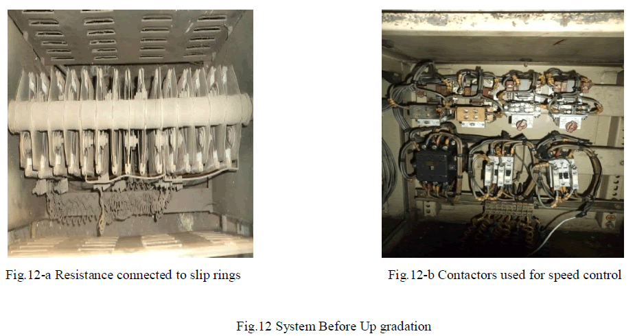
| In system before upgradation the speed control of Overhead crane was done by using two slip ring Induction motors whose rotor windings are connected to power resistances in 4 to 5 steps by power contactors. Reversing is done by changing the phase sequence of the stator supply through line contactors. Braking is achieved by plugging. Limitation of this system is variation of speed can be done in three steps only and if different speed range is required then resistances should be replaced with different values. This system requires frequent maintenance and provides less efficiency. Therefore this creates need for new mechanism which can overcome these disadvantages. There were three options for system improvement-buy a new crane, refurbish used crane or upgrade the present crane. Rather than scrap out an old system which is still structurally sound, this system is upgraded by using Variable frequency Drive supplied by squirrel-cage induction motors for all types of motion. |
II. SYSTEM BEFORE UPGRADATION |
A. Working of System: |
| Two Slip Ring Induction Motors are used for overhead crane controlling. Slip Ring motor has a stator and a rotor with insulated windings brought out via slip rings and brushes. However, no power is applied to the slip rings. Their sole purpose is to allow resistance to be placed in series with the rotor windings while starting. This resistance is shorted out once the motor is started. |
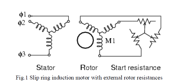 |
| Placing resistance in series with the rotor windings not only decreases start current, locked rotor current (LRC), but also increases the starting torque, locked rotor torque (LRT). Fig.2 shows that by increasing the rotor resistance from R0 to R1 to R2, the breakdown torque peak is shifted left to zero speed. This torque peak is much higher than the starting torque available with no rotor resistance (R0) Slip is pro |
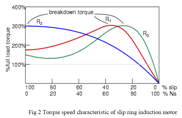 |
| The resistance decreases the torque available at full running speed. But that resistance is shorted out by the time the rotor is started. A shorted rotor operates like a squirrel cage rotor. Heat generated during starting is mostly dissipated external to the motor in the starting resistance. This motor is suited for starting high inertial loads. A high starting resistance makes the high pull out torque available at zero speed. |
B. Disadvantages of System before upgradation: |
| ïÃâÃâ Variation of speed can be done in three steps only. |
| ïÃâÃâ If different speed range is required then resistance should be replaced with different values. |
| ïÃâÃâ Initial and maintenance cost of Slip Ring motor is more compared to squirrel cage motor because of presence of slip rings, brushes, short circuiting devices etc. |
| ïÃâÃâ Less efficiency. |
III. METHODS FOR SPEED CONTROL OF SQUIRREL CAGE INDUCTION MOTOR |
| 1. Changing Applied Voltage |
| 2. Changing Applied Frequency |
| 3. Changing Number of Stator Poles |
1. Changing Applied Voltage: |
| This method, even though easiest, it is rarely used. The reasons are |
| (a) For a small change in speed, there must be a large variation in voltage. |
| (b) This large change in voltage results in large change in flux density, thereby seriously disturbing the magnetic distribution/condition of the motor. |
2. Changing Applied Frequency: |
| Synchronous speed of the induction motor is given by |
 |
| From this relation motor synchronous speed of motor is directly proportional to input frequency, thus the speed of the induction motor can be varied by varying input frequency [2]. |
3. Changing the number Of Stator Poles: |
| Number of poles is inversely proportional to the speed of the motor. This change in number of poles can be achieved by having two or more entirely independent stator windings in the same slots. Each winding gives a different number of poles and hence different synchronous speed. For example, for the same motor, if no of poles= 2, 4 or 6which can be changed as per speed requirement, and let the supply frequency f=50 Hz, |
| Then for |
| No. of Poles P = 2, then Ns = 120 * 50/2: So Ns = 3000 rpm |
| No. of Poles P = 4, then Ns = 120 * 50/4: So Ns = 1500 rpm |
| No. of Poles P = 6, then Ns = 120 * 50/6: So Ns = 1000 rpm |
| But numbers of poles for a motor are fixed at the time of manufacturing only. Therefore this is not a practical method. |
IV. PROPOSED SYSTEM ARCHITECTURE |
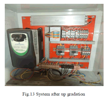
| For convenience, cost-efficiency, and precision, frequency variation method for speed control of motor is preferred. In proposed system two Slip ring Induction motors are converted into Squirrel Cage Induction motors by shorting its slip rings. External Resistances and contactors are replaced by Variable Frequency Drive.VFD is used to achieve variable speed by varying input frequency. Whenever we want to stop movement of crane thrusters Brakes is provided. |
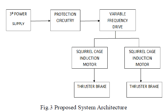 |
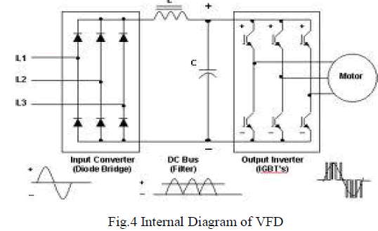
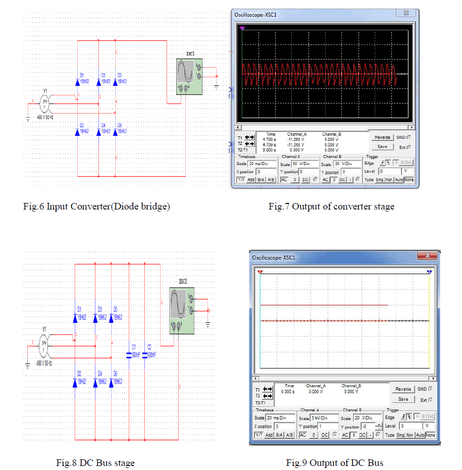
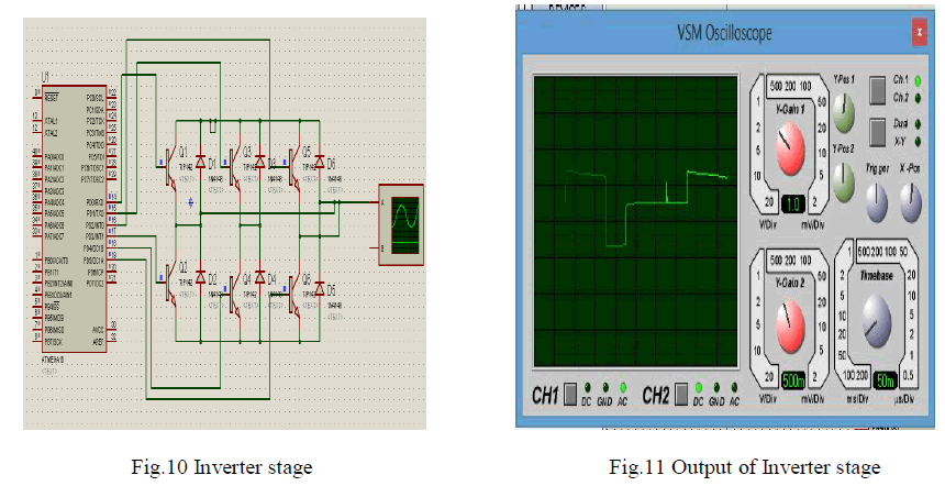
| As depicted in Fig. 1, Variable Frequency Drive is the heart of the system. Variable Frequency Drive (VFD) rectifies and filters AC power to create a DC power supply. The DC power supply feeds an inverter circuit that creates 3-phase AC output power of the frequency required to operate the motor at the desired speed [1]. The output voltage is proportional to the output frequency as required to allow the motor to develop rated torque at any operating speed.VFD designs use pulse width modulation in the inverter section to control the voltage. |
 |
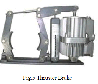
| Thrusters brake is a device to retard the speed of moving machinery and to stop it accurately to the desired position. The braking force is applied to the brake shoes by a pre-stressed compression spring. The shoes press on the rotating brake drum retarding its speed, and finally stopping it. The releasing of the brake and compressing of the spring is done by thrusters. |
 |
V. SIMULATION AND RESULTS |
| We have simulated converter and filter using Multisim version 8and Output Inverter stage is simulated using Proteus software. Results are as shown in below figures. |
 |
 |
VI. PERFORMANCE EVALUATION |
 |
 |
 |
A. Achieved Objectives: |
| 1. VFD reduces high starting current of Ac induction motor and thus minimizes effect of shock on both load and equipment. |
| 2. Programmable acceleration and deceleration produce softer start and stop and assure smooth transition between speed steps and greatly reduce brake wear and maintenance. |
| 3. Ease of Fault Diagnostic |
| 4. Reduced Failures due to Slip Ring Brushes eliminated |
CONCLUSION |
| In this paper we presented how a cost effective solution for controlling of overhead crane can be easily implemented by upgrading existing system with Variable Frequency Drive. |
ACKNOWLEDGMENT |
| We thank our teachers for their continuous support and encouragement in this work, for cultivating new and aspiring ideas in our mind. We would especially thank Mrs. Ashwini S.Shinde for guiding us throughout the process and being available for any problem faced. |
References |
|