Research & Reviews: Journal of Material Sciences
ISSN:2321-6212
ISSN:2321-6212
Tout N Moja1*, Yen T Tsai3, Shivani B Mishra2, Shyh-Shin Hwang4, Ajay Kumar Mishra2
1 Nanotechnology and Water Sustainability Research Unit, Johannesburg, South Africa
2 Department of Applied Chemistry, Durban University of Technology, Durban, South Africa
3 Department of Mechanical Engineering, Chien-Hsin University of Science and Technology, Taoyuan City, Taiwan
4 Department of Chemistry, Chung Yuan Christian University, Taoyuan City, Taiwan
Received: 29-Jul-2024, Manuscript No. JOMS-24-144286; Editor assigned: 01-Aug-2024, PreQC No. JOMS-24-144286 (PQ); Reviewed: 15-Aug-2024, QC No. JOMS-24- 144286; Revised: 22-Aug-2024, Manuscript No. JOMS-24-144286 (R); Published: 29-Aug-2024, DOI: 10.4172/2321-6212.12.3.002
Citation: Moja TN, et al. Use of Graphene (GP)/Nylon 6 (PA6) Nanocomposite for Remediation of Cadmium(II) Ions from Aqueous Solutions. RRJ Mater Sci. 2024;12:002.
Copyright: © 2024 Moja TN, et al. This is an open-access article distributed under the terms of the Creative Commons Attribution License, which permits unrestricted use, distribution, and reproduction in any medium, provided the original author and source are credited.
Visit for more related articles at Research & Reviews: Journal of Material Sciences
Graphene (GP) is reinforced with Nylon 6 (PA6) composites were synthesized by melt mix extrusion and moulded through microcellular injection technique. PA6/GP nanocomposites were fabricated for adsorption application for removal of Cd(II) metal ion. The structural morphologies of all samples evaluated on X-Ray Diffraction (XRD), Scanning Electron Microscopy (SEM), and TGA illustrated the thermally stable, and crystallized materials with pore-like cells. Scanning Electron Microscopy (SEM) analysis at low magnifications showed neat PA6 experienced porous-like fracture and had rough surface after introduction of foaming agent, whilst nanocomposite (PA6/GP) samples had rough, grainy surface indicating extensive deformation within the matrix complex. The storage modulus can exhibit the stiffness of the material and tan δ indicates the glass transition temperature of the composites. The storage modulus is 2399, 2622, 2775, 3221 MPa at 60â for the neat PA6, 0.5, 1, 3 wt% GP, respectively. Furthermore, the removal of Cd(II) with PA6/GP 3.0 wt% composite was found to follow the Langmuir isotherm model with a 99.9% removal efficiency. The results indicated that PA6 1.0 wt% composite can be efficiently used as a superabsorbent for the removal of Pb(II) from aqueous solution.
Polymer composite; Graphene; Polyamide (PA6) Heavy metals; Adsorption; Kinetics
The use of adsorption technique is implemented in this study for the remediation of cadmium Cd(II) metal ions from aqueous solutions. According to the World Health Organizations (WHO) and United States Environmental Protection Agency (USEPA) and South African National Standard 241 (SANS 241) Cd(II) permissible limit in drinking water is 0.05 mg/L.
Adsorption efficiency found via adsorption properties such as ion exchange and the high surface etc. [1-5]. It is off high importance to dispose of Cd(II) because it is toxic even at low concentrations. A number of investigations for the remediation of Cd(II) metal ions from wastewater were conducted using different techniques. However, Adsorption is the most effective technique. Graphene (GP) is used as a filler material to enhance adsorption capacity. Due to its adsorption capacity, and low cost makes it favorable for application in water. Due to this reasons, Polyamide (PA6) [6] was used to improve GP to increase the surface area and active site for an effective adsorption of Cd(II) ions [7,8]. The effectiveness of graphene/nylon 6 polymer composite was determined using different modified clay; improved dosage, solution pH and time [9]. The incorporation of graphene in nylon 6 adsorbent increases its compressive strength, surface area and morphology [10-12]. The large-scale production of functionalized PA6 at low cost should result in good adsorbents for wastewater purification.
Materials
Nylon or Polyamide 6 (PA6), 2100, with melt flow index 45 g/10 min and density 1.13 g/cm3 was supplied by Na-Ya Plastics Co. Ltd, Taiwan. Master batch of 3.0 wt% Graphene under 100 nm magnification (Figure 1) was supplied by Enerage Co. Ltd, Taiwan.

Figure 1: A schematic diagram of micro-cellular injection molding setup.
Compounding and foaming process
PA6/Graphene nanocomposites were diluted into 0.5, 1.0 and 3.0 wt% from master batch of 3 wt%. Then, the nanocomposites were molded into dog-bone specimen separately using conventional and Mucell® injection molding processes. The microcellular injection molding process was performed on a 100-ton ARBURG-420 C injection molding machine, equipped with a microcellular foaming system. Nitrogen was used as a physical blowing agent in the foaming process ‘foam’ and the other parameter was applied without the presence of the blowing agent “non-foam” as stated in Table 1. The processing parameters for both conventional and microcellular moldings are presented in Table 1.
| Processing | Non-Foam | Foam |
|---|---|---|
| Melt temp. (℃) | 290 | 290 |
| Mold temp. (℃) | 90 | 90 |
| Injection speed (cm3/s) | 140 | 150 |
| Injection P. (Bar) | 1000 | 700 |
| V/P (cm3) | 3 | 1 |
| Packing P. (Bar) | 700-600 | 200 |
| Packing time (s) | 5 | 0.5 |
| Shot size (cm3) | 22.5 | 17.5 |
| Screw speed (m/min) | 25 | 25 |
| Back P. (Bar) | 50 | 110 |
| Cooling time (s) | 25 | 25 |
| SCF (s) | - | 3 |
Table 1. Process parameters for PA6/Graphene composite.
Effect of variable parameters
Effect pH: The adsorption capacity of the PA6/GP composites was determined by changing the pH of solution at a range of 2, 4, 6, 8 and 12 while the other parameters were maintained as explained in abovementioned experiment.
The solutions used to control pH of the solution were 0.125 M HCl and 0.125 M NaOH.
Effect of initial concentration: The effect of the initial concentration of the model contaminants on the adsorption capacity of the PA6/GP composite was studied by varying the initial concentrations of Cd(II) from 10, 20, 30, 40, and 50 ppm. Other parameters were kept constant.
Effect of adsorbent weight on adsorption of Cd(II): To investigate the effect of adsorbent mass on the rate of adsorption. 0.02 g, 0.1 g, 0.15 g and 0.2 g of PA6/GP composites masses were varied by mixing with aqueous solution in a mechanical shaker. Other parameters such as pH, temperature, contact time and concentration were kept constant.
Effect of contact time: Time was also varied for adsorption capacity using PA6/GP composite. Time range of 5, 15, 30, 45, 180, 240 and 1440 minutes was used. Other parameters such as pH, temperature, and concentration were kept constant.
Batch equilibrium studies
A 100 ppm stock solution of Cd(II) solution was prepared by dissolving lead nitrate and cadmium nitrate salts in deionized water. Batch adsorption experiments were conducted to study the effect of pH, contact time and initial concentration and dose on Cd(II) adsorption. For all the experiments adsorbent weight was fixed to be 0.050 g except on the studies on the effect of pH, and dosage where the weight was 0.150 g and the volume of Cd(II) solutions were fixed at 15 ml. Initial pH of the solution was adjusted using 0.125 M NaOH or HCl. The initial concentration range of 10 ppm to 50 mg/l was used. The solution was shaken thoroughly by a mechanical shaker rotating at 250 rpm and filtered using a whatman filter paper at different time interval. After adsorption, the residual metal pollutant was determent by ICP-OES (Agilent 720 series).
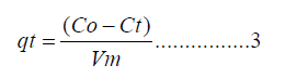
The amount of metal adsorbed (qe) and percent of removal (%R) can be calculated using the following equations
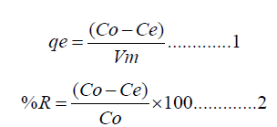
Where (qe) is the amount of metal pollutant adsorbed (mg/g), Co and Ce are the initial and equilibrium concentrations of the metal pollutant, respectively. (V) is the volume of the solution in liters and (m) is the weight of the polymer composite used in grams (g).
Batch kinetic studies
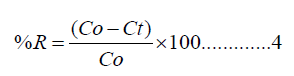
Kinetic experiments were identical to equilibrium experiments except for the variation of time. Further, the remaining concentration after adsorption was converted to adsorption capacity by
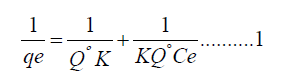
Where Ct is the remaining concentration (mg/l) at time (t). (V) is the volume of the solution in liters, and (m) is the weight of the polymer composite used in grams (g). The percent Cd(II) removed. R (%) was calculated using equation (4)
Characterization
X-ray diffraction was carried out on a PANalytical PW3040/60 X'Pert Pro, with Cu Kα radiation (45 kV, 40 mA) and wavelength λ=1.54 Å. The scan angle covered 2º<2θ<70º for layer materials and composites at a scan speed of 3 min-1. The thermal decomposition temperature was determined by Thermo Gravimetric Analysis (TGA) (SII TG/DTA6200) and the experiment was performed by samples (10 mg) of air gas flow from 40ºC to 900ºC at a heating rate of 10ºC min-1. The Dynamic Mechanical Analysis (DMA) was carried out with a TA-Q800 instrument with sample size: 35 mm × 12 mm × 3 mm in the air at a scanning range. The dispersion morphology of PA6 composites was measured by JEOL JSM-6500F Scanning Electron Micrographs (SEM). Tensile strength performed with Tensile Testing Machine Come tech D638 instrument. Analysis of metal trace was achieved by Inductive Coupled Plasma (ICP-OES) model 720 series.
Morphology of PA6/GP composite
The structural morphology of PA6/GP were characterized using the XRD, TGA and SEM analysis. The XRD figure of PA6/GP is illustrated in Figure 2 below. In the figure, XRD identifies the change of the interlayer distance or appears on new peaks on composites with influence of nanomaterials. The characteristic basal peak of graphene showed at 26.47º (0 0 2) [13]. The intensity peak of graphene increases as the content of the polymer dose increases which shows the graphene is more oriented. From the figure illustrated below, the results indicate that GP has intercalated in the polymer matrix.

Figure 2: XRD pattern of PA6 and PA6/GP nanocomposites.
SEM is applied as a tool to analyse surface morphology of PA6 and the effect of incorporation. In Figure 3 below, low, and high magnification pictures of nanocomposite (reinforced with GP) and PA6 surfaces are illustrated [14]. At low magnifications neat PA6 demonstrated a permeable-like fragmentation and an irregular surface morphology after the incorporation of a foaming agent, however, nanocomposite images indicated an irregular, granular surface illustrating a thorough deformation within the complex of the matrix. The scattering of GP in PA6 matrix is clear from hollow-like structures that appear to be permeable in the interior of the polymer matrix.

Figure 3: SEM images of PA6 neat and PA6/GP nanocomposites.
Thermo-mechanical characterizations of PA6 nanocomposites
In Figure 4, the storage modulus and tan δ for nanocomposites is illustrated, respectively. The storage modulus can display the toughness of the nanocomposite and tan δ shows the glass transition temperature of the nanocomposites [15]. The storage modulus is 2399, 2622, 2775, 3221 MPa at 60℃ for the neat PA6, 0.5, 1, 3 wt% GP, respectively. When relating these two adsorbent materials, the nanocomposite has a superior storage modulus than neat PA6. This it because the concentration of GP increase in the polymer matrix.

Figure 4: Storage module of PA6/GP nanocomposites.

The DSC thermograms of the nanocomposites outcomes are potted in Table 2, with the Melting Temperature (Tm) and the Cooling Crystal Temperature (Tcc) of the nanocomposites. It indicates that the nanocomposites Tm were nearly similar after the incorporation of GP in the PA6 polymer. Nonetheless, Tcc was greater for GP filler, showing that GP assisted with its crystallization.
| Sample | Td (ºC) | Tcc (ºC) | Tm (ºC) | ▲H (J/g) | ▲Hc (J/g) |
|---|---|---|---|---|---|
| PA6 | 470 ± 0.3 | 182.62 | 224.49 | 36.71 | 47.57 |
| PA6+GP 0.5 wt% | 468 ± 0.5 | 184.97 | 222 | 48.59 | 52.46 |
| PA6+GP 1 wt% | 469 ± 0.1 | 186.68 | 221.34 | 49.94 | 53.62 |
| PA6+GP 3 wt% | 471 ± 0.2 | 186.83 | 221.39 | 48.8 | 51.27 |
Table 2. Thermo-mechanical properties of PA6 nanocomposites.
TGA evaluation of the nanocomposites are as shown in Figures 5. The thermal stability of PA6/GP nanocomposites and the Thermal Decomposition (Td) temperature were reduced as correlated with that of neat PA6. Although the thermal degradation temperature lessened for PA6/GP nanocomposites. This was due to poor interface of bonding between GP and PA6 conditions.

Figure 5: TGA curves of PA6 nanocomposites.

Mechanism
Figure 6 below illustrates the probable bonding mechanism among PA6 and GP nanoparticles for remediation of cadmium divalent metal ions. As demonstrated below, PA6 were intercalated within graphene via covalent bonding. Therefore, a nanocomposite is designed with enhanced structural and chemical morphology for remediation of Cd(II) ions. PA6 is a good adsorbent with N-H functional groups and is immensely permeable while graphene has a high negative charge and a good sorbent for adsorption heavy metals. At pH 6 adsorption efficiency of Cd(II) comes to equilibrium, this could be due an enhanced surface area and surface charge alteration of the adsorbent. As a result, the sudden decrease in efficiency of Cd(II) at pH<7 is assigned to the composition of Cd(OH)2, which causes forces of repulsion between adsorbent and adsorbate. The assumption can be taken from the outcomes in Figure 7, which shows that the favourable pH values of the binary system to remediate Cd(II) from aqueous solution by using PA6/GP 3 wt% is pH 6.

Figure 6: Mechanism illustrating the possible bonding and removal of Cd(II) from aqueous solutions.

Figure 7: Concentration dependent performance characteristics of PA6/GP nanocomposites on Cd(II) adsorption at room temperature
Heavy metal uptake
Effect of concentration: The outcomes of initial concentration on the percentage of removal of Cd(II) by PA6/GP nanocomposites is shown in Figure 7. There are 5 different concentrations of Cd(II) applied for this experimental section i.e., 10, 20, 30, 40 and 50 mg/L with a continuous dosage of 0.01 g of adsorbent. The ability of PA6/GP to uptake Cd(II) is assigned to the presence of amide (NH-), ion charge and the swelling ability. The PA6/GP 3 wt% nanocomposite was able to remediate up to 75% of Cd(II) at 40 mg/L. This may be due to the high porosity of nanocomposite exhibited by the foaming agent, which means there are more active sites for adsorption [16]. Therefore, PA6/GP 3 wt% nanocomposite was used for further application due to its immense uptake efficacy.
Effect of pH: Figure 8 demonstrate the outcomes of pH on Cd(II) of remediation efficacy using PA6/GP 3 wt% nanocomposites. The percentage of removal rises with the amount of pH to achieve equilibrium at pH 6 using PA6/GP 3 wt% adsorbent. Nonetheless, as pH reduces, there is a sudden fall on the uptake efficacy from pH 7 onwards. The overall remediation of Cd(II) ions was observed at pH 6 with 99.5 % efficacy, using PA6/GP 3 wt% nanocomposite [17]. The mechanism of pH relies on Cd(II) uptake, as indicated in previous experimental, toxic metal ions uptake can be divided into three different steps, Viz., hydrolyses: When pH>6, adsorption or surficial remediation when 5<pH<6, and competitive adsorption between Cd2+ and H3O+ when pH<5 [18]. Thus, the outcomes in Figure 8 advocates that remediation of Cd(II) ions is favorable via adsorption or surficial deposition. Hydrolyses of Cd(II) is likely to reduce absorption of free Cd(II) ions [19].

Figure 8: pH dependent performance characteristics of PA6/GP 3 wt% nanocomposite, on Cd(II) adsorption at 40 mg/L and 25ºC.
Effect of adsorbent weight on adsorption of Cd(II): When observing the removal of Cd(II), Figure 9 illustrates the increase of uptake efficacy as the adsorbent dose was increased. This is due to more active sites availability for PA6/GP 3 wt% nanocomposite. The equilibrium was at a remediation efficacy of 96.6% for Cd(II) ions. Hence, addition of mass increased the efficacy. The outcomes of adsorptive remediation of toxic metals ions with respect to adsorbent dosage is shown in Figure 9.

Figure 9: Dosage dependent performance characteristics of PA6/GP 3 wt% nanocomposite with Cd(II) uptake at 40 mg/L pH 6 and room temperature. 
Effect of contact time: Figure 10 below, demonstrate the difference in percentage remediation of Cd(II) over a period range of 5, 10, 15, 20, 25, 30, 35 and 40 minutes using 0.03 g of PA6/GP 3 wt% nanocomposites with pH 6, 40 mg/L Cd(II) initial concentration as constants. From Figure 10, the optimal remediation of Cd(II) changed on the uptake of Cd(II). The experimental is related to Zhu et al., where the chart shows a rise in Cd(II) remediation efficacy as time increases [16,20]. The maximum remediation of Cd(II) was achieved within 25 min with a percentage remediation at 95%, 55% using PA6/GP 3 wt% nanocomposite. After 25 min the nanocomposite reaches equilibrium and shows no more intake of the pollutant.

Figure 10: Time dependent performance characteristics of PA6/GP 3 wt% nanocomposite, on Cd (II) adsorption at 40 mg/L, 0.03 g at 25ºC. 
Isotherms models
Langmuir isotherm: The Langmuir isotherm model demonstrates a continuous accumulative surficial inhabitation as a value of pressure through the completely surficial area is enclosed with a singular layer of atoms and no more adsorptions can materialize [21]. Furthermore, it is built on the theory that when an atom is adsorbed on an active site, other atoms cannot adsorb at the same site. Thus, contains monolayer adsorption, no interface between the adsorbed atoms [22]. Gupta and Babu illustrate the non nonlinear formula of Langmuir isotherm, indicated in equation 1 below.
Where qe and k is the concentrations adsorbed and Langmuir constant, respectively. (dm3/g) is maximum conc. of Cd(II) in mg/L and Qmax is the monolayer capacity of the prepared nano sample (mg/g), by drawing  a linear slope derived and Langmuir isotherm constants are extracted on it. As shown in Figure 11 and the outcomes are given on Table 3.
| Langmuir isotherm | Freundlich isotherm | Temkin isotherm | ||||||||
|---|---|---|---|---|---|---|---|---|---|---|
| Metal ions | Qmax | RL | K | R2 | Kf | N | R2 | bt | AT | R2 |
| Cd(II) | - | 0.01 | 5.7 | 0.98 | 2.72 | 5.26 | 0.951 | 97.82 | 1.075 | 0.951 |
Table 3. Isotherms constants and correlation coefficients for adsorption of Cd(II) from aqueous solution.

Figure 11: (A) Langmuir isotherm (B) Freundlich isotherm (C) Temkin isotherm for Cd(II) removal using PA6/GP 3 wt%
nanocomposite. 
In the experiment,  against Ce plot produces a linearized graph with correlation coefficient R2=0.98, illustrating that remediation of the pollutant on PA6/GP 3% wt nanocomposite satisfy Langmuir isotherm as given in Figure 11 A [23].
Moreover, the segregation factor RL of Cd(II) detailed by equation 2, was measured with Langmuir isotherm parameters and achieved at 0.998.
against Ce plot produces a linearized graph with correlation coefficient R2=0.98, illustrating that remediation of the pollutant on PA6/GP 3% wt nanocomposite satisfy Langmuir isotherm as given in Figure 11 A [23].
Moreover, the segregation factor RL of Cd(II) detailed by equation 2, was measured with Langmuir isotherm parameters and achieved at 0.998.
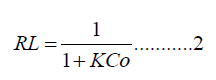
Where Co is the optimal concentration. mg/L of Cd (II) ions and K is the adsorption constant measured in 
Freundlich isotherm: The freundlich isotherm model assumes sorption route on heterogeneous adsorbent at equilibrium condition, for example, the involvement of various active sites through several sorption dynamisms. Choy McKay, and porter give the nonlinear form of Freundlich isotherm as
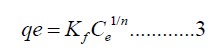
Logarithmically equation 3 is changed to
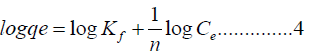
The linear logarithmic form of Freundlich isotherm model is prearranged by equation 5.
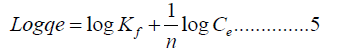
Kf is the Freundlich constant, and n is a dimensional constant signifying the magnitude of non-linearity between molecule absorption and sorption. A plot of log qe vs. log Ce is presented in Figure 11B PA6/GP 3 wt% nanocomposite [23]. The linearized graph illustrates an excellent correlation coefficient (>0.900) that indicates sorption satisfied the Freundlich isotherm model. However, in the study case, the graph illustrates a correlation coefficient R2 of 0.9506. Demonstrating that PA6/GP 3 wt% nanocomposite did not satisfy the Freundlich isotherm model. Moreover, the gradient of 1/n specifies the effect of concentration on the sorption efficacy and characterizes sorption intensity on all sorption calculated, as shown in Table 3.
Temkin isotherm: In the Figure 11C, a plot qe vs. ln Ce is observed. Which describe Temkin Isotherm to full capacity. Temkin isotherm entails heterogeneous surficial energy co-ordination (irregular circulation of heat sorption). By managing the volume of conc., the isotherm consider heat of sorption as a function of temperature (ΔH) in Kelvin for all molecules in the layer will decrease linearly relatively than logarithmic with analysis [23]. An equation below describes the uniform binding energy carried out by the plot qe vs. ln Ce.
Where R is general constant (8.314 J/mol/K), heat of sorption is abbreviated by B and measured in J/mol (constant), AT is a constant for Temkin isotherm at equilibrium binding calculated in L/g, and Bt are Temkin isotherm constant, and finally T is Temp in Kelvin.
The linear equation (5) above is changed to equation (6) below.
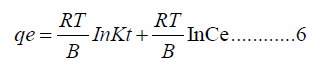
In Figure 11C, Temkin are measured. Where: BT=25.34 J/mol and AT=1.075 L/g, with correlation coefficient of R2=0.9506
Kinetic modeling.
Pseudo first order: Rate of reaction and mass transfer is examined by using the pseudo-1st order and pseudo-2nd order models for remediation of Cd(II) ions onto the polymer nanocomposites. Linearized equations applied for pseudo 1st order is as equation 7 below
where qe and qt concentrations of Cd(II) ions measured in mg/L, accumulated on the surface of PA6/GP 3 wt% at, Kad represents pseudo-1st-order constant in min-1. Cadmium Cd(II) ions were calculated from the linear plots of log (qe-qt) vs. t. A best-fit line plot is illustrated and the R2 obtained in the experiment as shown in Figure 12A. The correlation coefficient didn’t satisfy pseudo-1st order conditions, which then specified that the adsorption of Cd(II) ions onto PA6/GP 3 wt% was not favorable for pseudo-1st order.

Figure 12: (A) Pseudo 1st order model and (B) Pseudo 2nd order of PA6/GP 3 wt% for Cd (II) remediation.

Figure 12 illustrates the Pseudo 1st order and 2nd order of Cd(II) ions in aqueous solutions, which escalate from the start of the experimentations and acquired an equilibrium shortly. The duration needed to get to equilibrium rest on the pollutant to be adsorbed. The percentage of uptake efficacy reached <99.5% after 25 min for Cd(II).
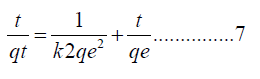
Pseudo second order: The equation below represents the pseudo-second order.
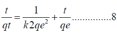
Where K represents the pseudo-2nd order constant rate, measured in g/mg min and h is the equivalent of kqe2, which is measured in mg/g min.
A linearized plot of t/q (t) vs. t (s) in Figure 12B represent pseudo-2nd-order model. For the experimental to follow kinetics the adsorption process of Cd(II) ions onto PA6/GP 3 wt%, correlation coefficient must be greater than 0.9 [23,24]. In the experimental conducted, the correlation coefficient of R2=1 for Cd(II) was achieved, indicating that in both cases sorption satisfied the properties of pseudo-2nd order model as illustrated in Table 3 [25].
Where qe and qt (mg/g) are the capacities of Cd(II), adsorbed at equilibrium and time t (min), respectively, k1 is the pseudo-first-order rate constant (min−1), and k2 is the pseudo-second-order rate constant (g/min).
PA6/GP nanocomposite was achieved using melt mix extrusion and moulded through microcellular injection technique. From the observation of XRD results, the instrumental analysis of PA6/GP nanocomposite indicates that graphene intercalated into the polymer matrix and PA6 experienced porous-like fracture with rough surface after introduction of foaming agent. whilst nanocomposite (PA6/GP) samples had rough, grainy surface indicating extensive deformation within the matrix complex confirmed by SEM, furthermore, storage modulus and tan δ for the PA6/GP nanocomposites was analyzed and the storage modulus was found at 2399, 2622, 2775, 3221 MPa at 60℃ for the neat PA6, 0.5, 1, 3 wt% GP, respectively. When comparing these two composites, the PA6/GP nanocomposites have a larger storage modulus than that of the neat PA6, it is due to the concentration of GP increase in the polymer matrix. PA6/GP 3 wt% nanocomposite was used to uptake Cd(II) metal ions from aqueous solutions. The adsorption Sorption of Cd(II) is strictly dependent on initial concentration and Alkaline. PA6/GP 3 wt% efficiently and effectively removed Cd(II) from aqueous solutions within 25 minutes with an overall removal percentage of 99.5% at pH 6. The removal of Cd(II) by PA6/GP 3 wt% nanocomposite was found to follow the Langmuir isotherm and partial freundlich isotherm, indicating that Cd(II) ions was adsorbed on homogeneous sites whose binding energies were uniform and consequently made a layer on the surface of the nanocomposite. The adsorption of Cd(II) onto the composites was found to follow pseudo-second order kinetics. It has been established that the removal of Cd(II) from aqueous solution is predominantly through chemical adsorption due to pseudo-second order kinetics.
We appreciate and acknowledge funding from the Institute for Nanotechnology and Water Sustainability (iNanoWS) in the College of Science, Engineering and Technology (CSET), University of South Africa and Chien-Hsin University of Science and Technology for assisting with characterizations of the composite material.
Tout N Moja drafting and revising the manuscripts substantial contributions to the conception, design, editing, revision of the work; Ajay Kumar Mishra, Shivani B Mishra, Shyh-Shin Hwang, Yen T Tsai are drafting, editing and critical revision, final approval of the manuscript. All authors have read and agreed to the published version of the manuscript.
[Crossref] [Google Scholar] [PubMed]
[Crossref] [Google Scholar] [PubMed]
[Crossref] [Google Scholar] [PubMed]
[Crossref] [Google Scholar] [PubMed]
[Crossref] [Google Scholar] [PubMed]