ISSN ONLINE(2278-8875) PRINT (2320-3765)
ISSN ONLINE(2278-8875) PRINT (2320-3765)
Sunil Kumar 1, Shivani Sehgal 2, Sagar Bhosle 3
|
| Related article at Pubmed, Scholar Google |
Visit for more related articles at International Journal of Advanced Research in Electrical, Electronics and Instrumentation Engineering
This paper deals with the application of an Self-Excited Induction Generator SEIG in a small wind power conversion system (WPCS). Such conversion system has capability to supply power demand of the loads with constant voltage and frequency, for which a power managing method is proposed. Voltage Sourced Converter (VSC) along with Battery Energy Storage System (BESS) is used to handle power flow between the SEIG and loads. The proposed control scheme, using a single voltage closed-loop control, is found to be suitable to regulate both voltage and frequency. A strategy for controlling the voltage and frequency of a wind generation system is presented in this paper. A mathematical model of wind generation system and synchronous generator has been developed and MATLAB model of the integrated system is developed for simulation studies under varying load conditions. It is found that a wind generation system along with a synchronous generator and STATCOM is able to maintain the voltage and frequency of the system constant. The synchronous generator helps in reducing the reactive power supplied by STATCOM and hence a reduced capacity STATCOM could be used for the purpose
Keywords |
| wind Power Conversion System, Battery Energy Storage System, STATCOM |
INTRODUCTION |
| In regulated Due to climate changes such as temperature rise due to increase in greenhouse gases (GHG) emission, increase in sea level, high oil price, depletion of fossil fuel reserves and growing in power demand, the world is obliged to search for new sources of energy on which the emission of GHG would be reduced to 5% from their 1990 level. These problems lead scientists towards new clean power conversion systems. The replenished energy resources are suitable to meet the clean power restrictions. Wind became an environmental-friendly and economically viable energy source. Self-excited induction generators (SEIG) are reported to be suitable for small scale wind power plants [1, 2] because of their advantages such as low price, robustness, ease of maintenance, self-protection, easy maintainability, availability and capability to produce electrical power even at variable speed [3, 4]. These may be operated on/off grid-connected. In off grid mode or Autonomous Wind Power Conversion System (AWPCS), SEIG is useful for supplying remote areas such as islands, military equipment, ships and small villages far from conventional resources. Major drawbacks in using SEIG are their poor voltage frequency regulation which depends upon generator speed, the amount of reactive power and the load nature. Literature provides information on several attempts that have been made to analyse the steady state, dynamic and transient behaviour of SEIG based standalone wind energy system [5 – 7]. To maintain constant output power at load terminals, many researchers have suggested control strategies and application of different power conditioning systems [8 – 11] for SEIG terminal voltage and frequency control. In the recent literature [12 – 18], the Battery Energy Storage System (BESS) with a Voltage Source Converter (VSC) is employed for isolated system. Methods have been proposed to regulate both the SEIG terminal voltage and frequency using two loop controls [14 – 18]. In [19, 20] an investigation has been carried out using modulation index to control the terminal voltage and load angle to control the system frequency. To minimize the number of control loops, a singleloop control was proposed in [21]. In the present work, an attempt has been made to control the terminal voltage and frequency of an autonomous SEIG driven by a wind turbine. Voltage at the point of common coupling PCC is controlled by modulation index ‘m’, while system frequency is imposed by VFC at the desired frequency by forcing phase angle of the VFC ‘delta’ at a desired value so that a single closed-loop control is used. VFC supplies reactive power demand of balanced loads and behaves as a power balancing system to adequately manage the power flow between the SEIG, BESS and power demand of the loads |
II.MATHEMATICAL MODELING OF WIND GENERATION SYSTEM |
| In this Mathematical models are necessary to represent physical system for their detailed analysis. A model must be realistic and yet simple to understand and easy to manipulate. These are conflicting requirements, realistic models are seldom simple and simple models are seldom realistic. Often, the scope of a model is defined by what is considered relevant. Features or behaviour that is pertinent must be included in the model and those that are not can be ignored. Modeling here refers to the process of analysis and synthesis to arrive at a suitable mathematical description that encompasses the relevant dynamic characteristics of system components, preferably in terms of parameters that can be easily determined in practice. |
A. Description of Wind Generation System |
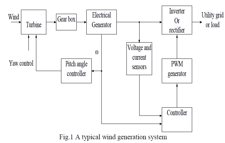 |
| Fig.1 shows a wind generation system. The main objective in wind energy conversion is to transform the wind energy into the rotation of a shaft. It consists of a wind turbine and a generator connected by means of a gear box. |
| As shown the wind turbine converts wind energy into mechanical energy, which then needs to be converted into the electrical form using generators. The electrical generator may be a synchronous or an induction generator. This electrical energy is transmitted to the grid by the stator winding of the induction generator. The pitch angle is controlled in order to limit the generator output power to its nominal value for high winds. In order to generate power the induction generators speed must be slightly above the synchronous speed. But the speed variation is typically so small that the WTIG is considered to be a fixed speed wind generator. The reactive power absorbed by the induction generator is provided by the grid or by some devices like capacitor banks, SVC, STATCOM or synchronous condenser. |
| The present trend is to adopt variable-speed operation of the wind turbines, because it has lots of benefits, the most important being the possibility of maximizing the power output. However, the resulting variation of voltage and frequency with the variation of wind speed necessitates the use of power electronics converters in order to obtain good quality power output. |
B. Pitch Angle Control |
| With pitch control it is possible to achieve a high efficiency by continuously aligning the blade in the direction of the relative wind. |
| On a pitch-controlled machine, as the wind speed exceeds its rated speed, the blades are gradually turned about the longitudinal axis and out of the wind to increase the pitch angle. This reduces the aerodynamic efficiency of the rotor, and the safe limit for the system, the pitch angle is so changed that the power output reduces to zero and the machine shifts to the ‘stall’ mode. After the gust passes, the pitch angle is reset to the normal position and the turbine is restarted. At normal wind speeds, the blade pitch angle should ideally settle to a value at which the output power equals the rated power. |
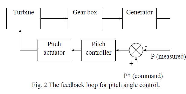
| The pitch angle control is shown in the fig.2. The input variable to the pitch controller is the error signal arising from the difference between the output electrical power and the reference power. The pitch controller operates the blade actuator to alter the pitch angle. During operation below the rated speed, the control system endeavors to pitch the blade at an angle that maximizes the rotor efficiency. The generator must be able to absorb the mechanical power output and deliver to the load. Hence, the generator output power needs to be simultaneously adjusted. |
 |
| Continuous pitch control is relatively expensive to incorporate, and the cost-benefit trade-off does not justify its use in small wind machines. However, the stalling mechanism must be incorporated to prevent damage of the turbine during turbulent weather conditions. |
| The pitch angle is given by |
| where, I is angle of inclination, |
| i is angle of incidence. |
| As I varies along the length of the blade, α should also vary to ensure an optimal angle of incidence at all points of the blade. Thus the desirable twist along the blade can be calculated easily. |
| The pitch angle should be such that tanε or CD/CL is minimum at all points of the rotor. It is more convenient to plot the curve for CD/CL versus i. Its minimum point will then represent the optimal value of the incidence angle. This method yields a twisted blade, that is, one that has different pitch angles at different distances from the axis. If the constraints in the production methods do not permit a twist, the optimal value of α can be chosen for a suitable point on the blade, say r = 0.8R, and the same pitch angle maintained throughout the blade. |
III.MATHEMATICAL MODEL OF WIND GENERATOR |
| Wind power generation, as it stands today, is dominated by induction generators, of both the squirrel cage type and wound rotor type. About 80% of the wind generators today are induction generators. |
A. Process of Self Excitation |
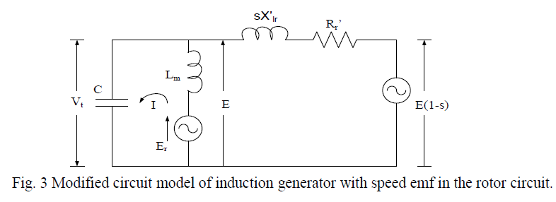
| For the self-excitation process to initiate a capacitor bank of suitable size must be connected across the machine terminals, the magnetic circuits of machine must retain some residual flux. In order to understand the selfexcitation process, let us refer to the simplified circuit model of the self-excited induction generator under no-load condition as shown in fig. 3 |
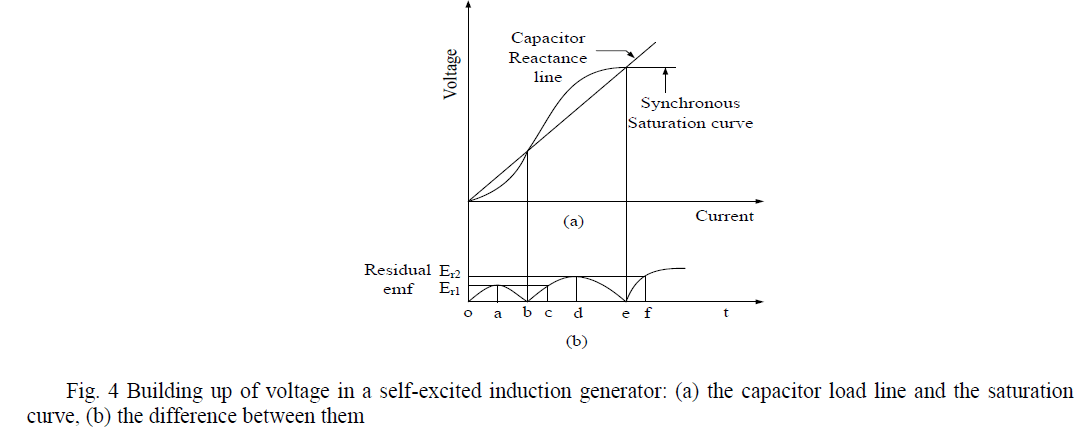
| For any speed of the rotor, the residual flux generates a small synchronous emf Er. The steady state magnitude of the current through the LmC circuit is such that the difference between the synchronous saturation curve and the capacitor load line, as shown in fig. 4, at this value of the stator current equals Er. |
 |
 |
| At this stage, the slip s being zero for no speed difference between the rotor and the air-gap flux, no induced rotor current flows and the machine operates as a synchronous generator. |
B. Effect of External Capacitance and Load Impedance on Performance of Induction Generator |
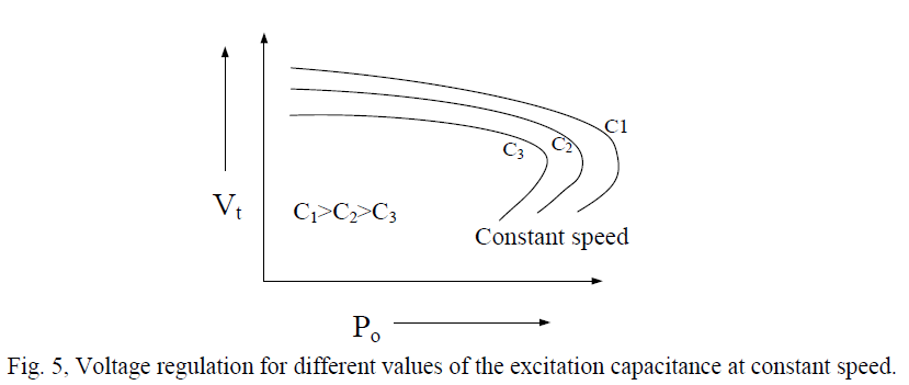 |
| The fig. 5, shows the typical variation of terminal voltage for resistive load with the output power at a fixed speed for different values of the excitation capacitance. The curves suggest that, for a given speed and capacitance, an optimal load impedance exists for maximum power output. In these respects, the curves are similar to the output characteristics of a dc shunt generator with different field circuit resistances. The frequency decreases with the load, but this variation is not significantly affected by the capacitance. |
 |
| Fig. 6 exhibits the manner in which the capacitance requirement changes with load and the power factor for constant terminal voltage at a fixed speed. The figure also indicates an increase in the VAR demand with decreasing load power factor. |
C. Effect of Speed Variation on Performance of Induction Generator |
| For power generation using wind energy, the speed of the prime mover varies over a wide range. For self-excitation, as indicated by the capacitance reactance value X F2 cb , the capacitor size is approximately proportional to the inverse of the square of the speed. The group of curves in fig. 7, shows some typical output characteristics for different speeds under the constraint 2 X v cb = constant. |
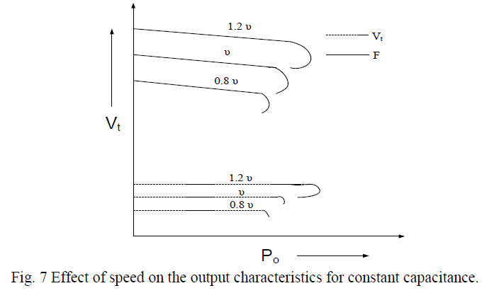 |
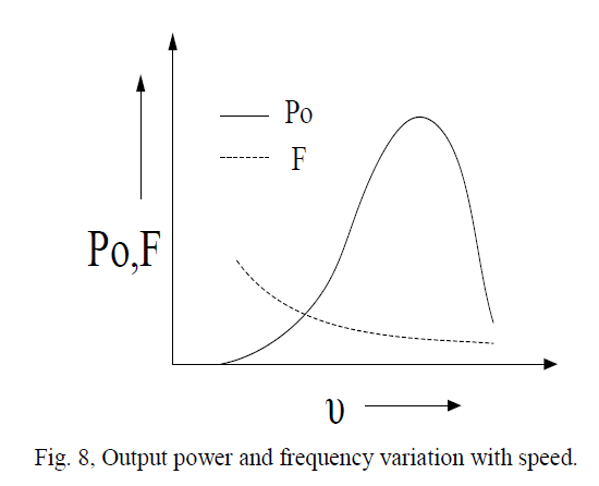
| The terminal voltage and the output frequency increase almost linearly with speed for the same power output over the working range. Fig. 8, shows the output power versus speed curves for a given capacitance and load impedances. From the figure it is clear that there exists a certain speed that maximizes the output power. |
 |
IV. RESULT AND DISCUSSION |
| Wind power farm connected to a weak grid system for defined load system. With change in load condition the power flow of the system (active & reactive power demands) changes with the variation of load. Since the wind farm and grid are defined for supplying the power for a defined load range. If extra load is added the power demand is not met as a result the synchronous machine/ the grid decelerate as a result frequency is reduced and hence more of the active power takes place. Thus resulting in high power losses. To overcome this problem STATCOM is included in the system which helps to increase the frequency and hence lower down the active power flow by supplying the additional reactive power. |
A. Performance of Wind Generation System without STATCOM |
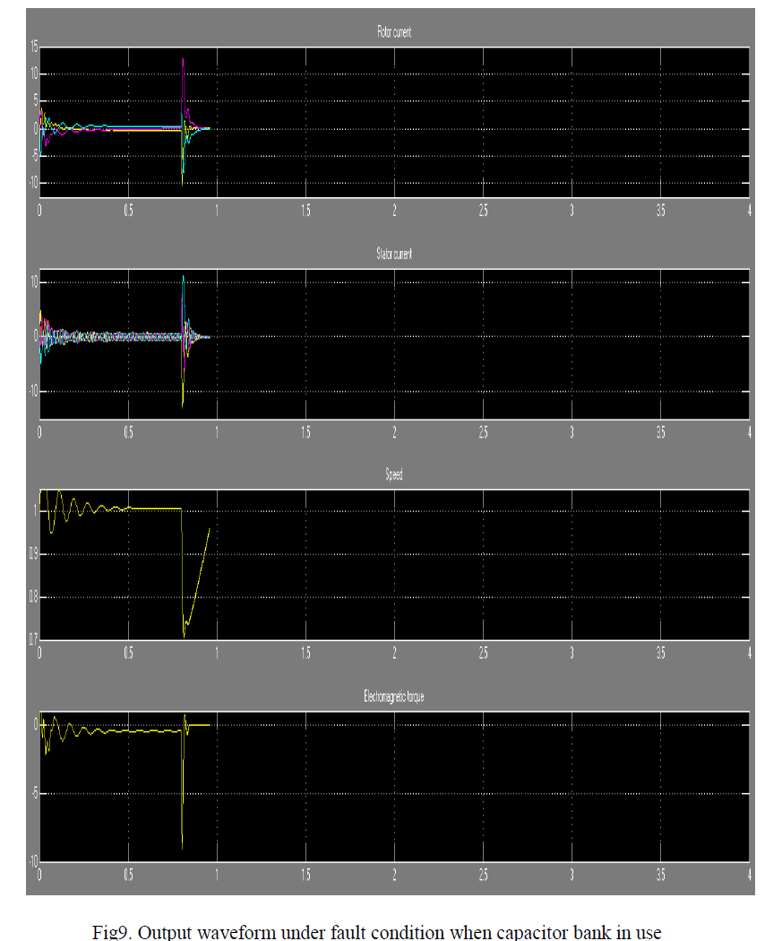 |
| When we consider the above model under fault condition the system become unbalance and uncontrolled in case of normal operating condition the output waveform is as shown in fig 9 during fault condition without use of STATCOM |
B. Performance of Wind Generation System with STATCOM |
| To overcome the difficulties arrives in case of power control by only use of capacitor bank the following model is structured by using STATCOM. The comparative result has been shown for the system under switching load characteristics. |
| The effective use of STATCOM is demonstrated for providing the reactive power support for the switching load. The result shows the effect of STATCOM on two ends (a) at the wind power generation (b) at the micro grid terminals |
| At the grid STATCOM helps to give better reactive power support hence regulating the defined power system. While at the generated wind power terminal where the STATCOM has been installed clearly the reactive power demand has been reduced hence maintaining the terminal voltage at the point of common coupling |
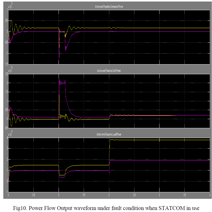 |
| Fig. 10, shows the performance characteristics of wind generator in a stand alone mode. The rating of the wind generator is 37 kW, 400 V, 50 Hz, 1480 rpm, driven by a wind turbine with pitch angle control running with a wind speed of 11 m/s. It is observered that when a load of 5 kW is switched on at t = 0.2 s. the terminal voltage of wind generator falls to 360 V. Also, due to variations in real power its frequency changes. |
| The STATCOM is responsible for generating the reactive power demanded by the load. A fixed excitation capacitor of 20 kVar is connected across the induction generator terminals. It is the minimum capacitance required for selfexcitation of the induction generator at no-load. |
VI.CONCLUSION |
| Thus In this investigation, a control strategy for controlling the SEIG terminal voltage and frequency has been presented. The simulation results show that when an induction generator is driven by a wind turbine alone it has poor voltage and frequency regulation. The turbine should also be pitch controlled to have constant speed. The minimum capacitance required for the induction generator self-excitation is selected. STATCOM shows the perfect control of the voltage and frequency. |
| The transients in the stator terminal voltage, stator current of induction generator are found to be acceptable for practical implementation. However, the realization of STATCOM for small wind generation unit may not be always economically viable. |
| If cost of the controller is not a major constraint, a STATCOM with a real power controller at its DC link is able to ensure constant voltage and constant frequency operation. STATCOM set frequency is imposed so; a voltage single closed loop control is used to maintain both voltage and frequency close to their desired values. Under several balanced loads and speed perturbations, the simulation results show the effect of perturbations on active/reactive power direction, SEIG terminal voltage and frequency. In each case the STATCOM has been found suitable with single-loop control to regulate the voltage and frequency and behaves as a free-slack to adequately manage power flow. The proposed wind power generating system can be used in the isolated rural, ships and mountainous areas far from the conventional source. |
References |
|