ISSN ONLINE(2278-8875) PRINT (2320-3765)
ISSN ONLINE(2278-8875) PRINT (2320-3765)
|
Visit for more related articles at International Journal of Advanced Research in Electrical, Electronics and Instrumentation Engineering
A system designed to prevent people from accessing firearms such as guns or pistols of an authorized person, so that the fire arms are not misused. In many cases these arms are misused by the authorized persons itself after the license period, so to overcome these defects we are discovering a new system in which we use a biometric system to detect the palm print of the person who owns it. There must be a license period for the fire arms and these license period say for one year is entered in the embedded microprocessor fitted in the firearm. A biometric system is essentially a pattern recognition system that makes use of biometric traits to recognize individuals. Palm is the inner surface of the hand between the wrist and fingers. Palm print is referred to as the principal lines, wrinkles and ridges on the palm. This system proposes Weber’s local descriptors based texture analysis of palm print. The hand palm print image is aligned and cropped according to the key points. The palm print image is enh anced and resized. The features of the palm print are compared with the database image feature vectors using correlation metric. If this module is completed successfully then the person info which contains person authentication number with four digits key will be matched with the extracted data from the already hidden image for second level security.
INTRODUCTION |
| It is a common story that weapons of policemen are stolen. A result of this is the use of these weapons for various crimes. It is not uncommon to see these weapons of law enforcement being used to break the law instead. The problem is that the pistols do not recognize their rightful owner and thus anybody who has the gun can use it freely. The need of the hour is of a system that checks the identity of the person who holds the gun before he can fire it. Similar to the problem is the theft of cars. People often misplace their car keys at their workplaces or eating places. By the time they come to know of it the car is gone. A system has to be designed that incorporates personal scanning in the key so that it operates only when it is in the hand of rightful owner.All the problems that we have listed so far have one common solution. A Wireless Link between two or more objects. For example in case of the pistol there will be a wireless link between the pistol and an object on the body of the policeman, say his badge. This means that the pistol will sense the badge before operating and it will work only if it gets the correct response from the badge. The pistol may depend on responses of a number of devices to make the pistol even more useless without these devices. Modules can be put in the badge, shoes and belt of the policeman and the pistol will operate only on a signal from all the three devices |
EXISTING SYSTEM: AUTHENTICATION MECHANISM BY USING THE RFID READER |
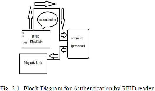 |
| The authentication can be done using RFID tag and reader. Licensed user will be provided with a tag with specific user ID. When weapon is set to validation RFID reader reads RFID tag. RFID reader sends the read data to microcontroller chip where authorizat ion of user is checked. If a person is authorized the microcontroller unlocks the gun by instructing magnetic locks. This method proved to be a failure because if the gun gets locked once, it is impossible to unlock it again. |
AUTHENTICATION BY USING FINGER PRINT SCANNER BLOCK DIAGRAM |
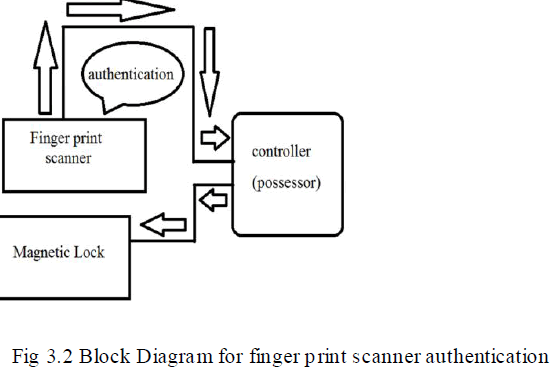 |
| The authorization of user can be checked by using finger print scanner. Finger print of user is scanned by finger print scanner. Scanner sends the data to microcontroller chip where authorizat ion of user is checked. If a person is authorized the microcontroller unlocks the gun by instructing magnetic locks. Tis method was a failure because finger print bluffing can easily be done and the database could not store a large value of samples. |
PROPOSED SYSTEM |
| Only the authorized person can access firearms.For this purpose 3D palm print recognition is usedAfter the expiry of license period, no one can access the firearm or the Weapon. Intimat ion is given to main person about the misuse of weapon through GSM. After the expiry of license period, the int imation is given to the authorised user through a message. |
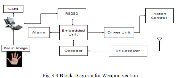
WEAPON SECTION BLOCK DIAGRAM |
| The weapon section consists of a camera to capture the images of palm prints and these images are sent to the PC. Thereby the authentication takes place in the PC .If this module is executed successfully, and then the microcontroller AT89S51 instructs the driver unit to unlock the piston control. The images from the database are encoded and received by the RF receiver and decoded and it is sent to PC through the RS232 cable. If unauthenticated person uses the gun, then the message is sent to the rightful user through GSM at he gun does not work in this case, instead the alarm rings. |
 |
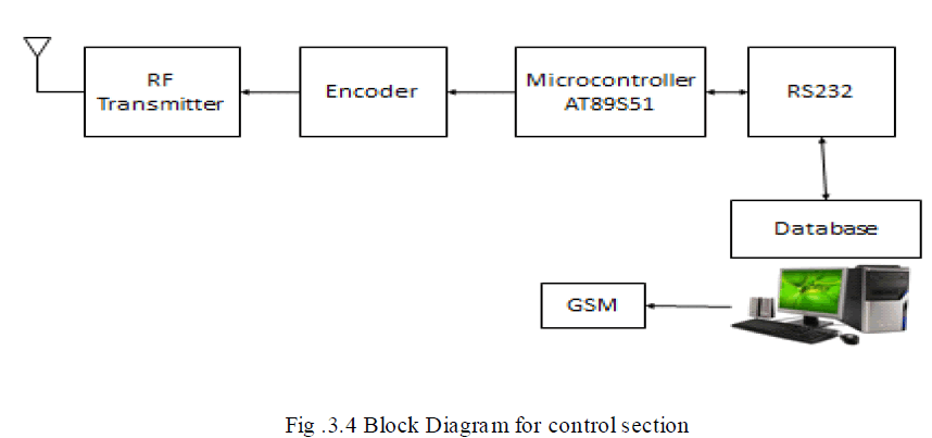
CONTROL ROOM SECTION BLOCK DIAGRAM |
| The control room section consists of a Database personal computer where the authenticated images are stored. The database is connected to the microcontroller AT89S51 by the RS232 cable. The RS232 cable consists of the MAX converter to convert the serial voltages into TTL outputs. The images in turn are to be compared at the weapon section. Thereby these images are encoded and are transmitted through the RF Transmitter and are received at the RF Receiver. In case of expiry of license of the gun, the license period is entered in the database and after this expiry, the pers on is unable to use the gun and the message is sent to the user or to the main person through GSM. |
 |
PALM PRINT CLASSIFICATION |
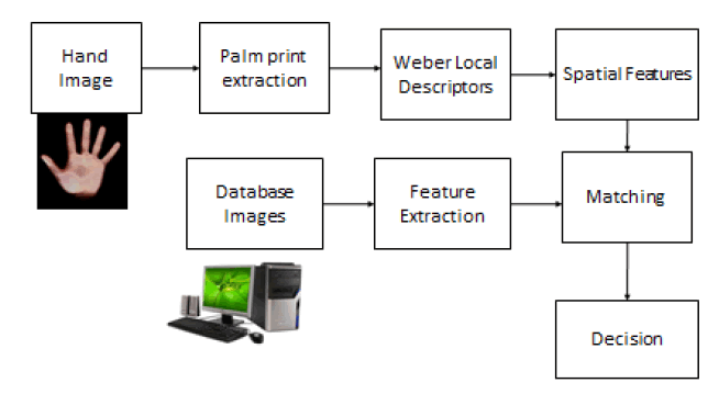 |
GSM |
| Global system for mobile communication (GSM) is a globally accepted standard for digital cellular communicat ions is the name of a standardization group established in 1982 to create a common European mobile telephone standard that would formulate specificat ion for a pan European mobile cellular radio system operating at 900MHz.GSM provides recommendations not requirements. The GSM specification defines the functions and interface requirements in detail but do not address the hardware. The reason for this is to limit the designers as little as possible but still make it possible for the operators to buy equipment’s from different suppliers. The GSM network is divided in to three major systems: The switching system (SS), The base station system (BSS), The Operation supporting system (OSS). |
GSM MODEM |
| A GSM modem is a wireless modem that works with a GSM wireless network. A wireless modem behaves like a dial-up modem. The main difference between them is that a dial-up modem sends and receives data through a fixed telephone line while a modem sends and receives data through radio waves. |
| A GSM modem can be an external device as a PC card/PCIMA card. Typically, an external GSM modem is connected to a computer through a serial cable or USB cable.as mentioned in earlier sections of this SMS tutorial, computers use AT commands to control modems. Both GSM modems and dial-up modems support a common set of standard AT commands. |
VOICE CALLS |
| Voice calls are not an application area to be targeted.in future if interface like a microphone and speaker are provided for some applications then this could be considered. |
SMS |
| SMS is an area where the modem can be used to provide features like: |
| Pre stored SMS transmissions. |
| This transmission can be transmitted on certain trigger events in an automation system. |
CONCLUSION |
| The project work has been completed successfully. The project work functions satisfactorily as per the design. The project work was developed after conducting a number of experiments before finalizing the design work, this reduced the bottle necks and we did not face much difficulty in the final integration process. In general the entire development of the project work was educative and we could gain a lot of experience by way of doing the project practically. We could understand the practical constraints of developing such systems about which we have studied by way of lectures in the theory classes. It was satisfying to see so many theoretical aspects work before us in real li fe practice, which we have the various processes that are involved in the weapon section and control room sections |
References |
|