ISSN ONLINE(2319-8753)PRINT(2347-6710)
ISSN ONLINE(2319-8753)PRINT(2347-6710)
Saravanan.A1, Subhashini.A2 , Dineshkumar.P3
|
| Related article at Pubmed, Scholar Google |
Visit for more related articles at International Journal of Innovative Research in Science, Engineering and Technology
The major objective of this project is to build up a device for wireless power transfer (WPT). Wireless power transfer can make an extraordinary change in the field of the electrical engineering which eliminates the use of conventional copper cables and current carrying wires. WPT is based on strong coupling between electromagnetic resonant objects to transfer energy wirelessly between them. The tuned magnetic fields generated by the primary coil can be arranged to interact vigorously with matched secondary windings in distant equipment but far more weakly with any surrounding objects or materials such as radio signals or biological tissues. But for very long distances, microwave transmission is used for the effective transfer of power.
Keywords |
| wireless power transfer (WPT) ,magnetic fields , microwave transmission and electromagnetic resonant. |
I.LITERATURE SURVEY |
| The concept of wireless electricity is not new. In fact it dates back to the 19th century, when Nikola Tesla used conduction based systems instead of resonance magnetic fields to transfer wireless power. |
| In 1905, Nikola Tesla with a team of construction workers in the small village of Shoreham, New York labored to erect a truly extraordinary structure. Over a period of several years the men had managed to assemble the framework and wiring for the 187-foot-tall Wardenclyffe Tower, in spite of severe budget shortfalls and a few engineering snags. The project was overseen by its designer, the eccentric-yet-ingenious inventor Nikola Tesla. Atop his tower was perched a fifty-five ton dome of conductive metals, and beneath it stretched an iron root system that penetrated more than 300 feet into the Earth's crust. |
| In 2007, Soljacic's team has done is that they have specifically tuned the transmitting unit to the receiving device. The transmission is also not hindered by the presence of any object in the line of sight. If the object to be charged is in the vicinity of the WiTricity source, then the energy transfer will undoubtedly take place. In this 'coupling resonance' system, the electric energy that is not used up by the receiver does not get radiated into the surrounding environment, but remains in the vicinity of the transmitter. |
| In 2010, Ick-Jae Yoon demonstrated that electrically small antennas can be designed to approach the recently derived theoretical bounds for wireless power transfer. Short dipole coupling is first simulated to determine the antenna design specifications for efficient coupling beyond the coupled mode region. Electrically small (kr=0.31) but highly efficient folded cylindrical helix dipoles with 50- input impedance are designed. The power transfer efficiency between two Such antennas is simulated for the collinear and parallel configurations. Two folded cylindrical helix dipoles are constructed, and the power transfer efficiency between them is measured and compared to the simulation. The measured results show a power transfer efficiency of 40% at a distance of 0.25 (0.39 m at 195 MHz) in the collinear configuration. |
| In 2011, Fei Zhang explored a technology in Wireless power transfer using strongly coupled electromagnetic resonators. Although this technology is able to transmit electrical energy over a much longer distance than traditional near field methods, in some applications, its effective distance is still insufficient. In this paper, we investigate a relay effect to extend the energy transfer distance. Experiments are conducted to confirm the theoretical results and demonstrate the effectiveness of the relay approach. This approach significantly improves the performance of the present two-resonator system and allows a curved path in space to be defined for wireless power transfer using smaller resonators. |
| In 2012, Ram Rakhyani A.K. proposed an inductive link based wireless power transfer (WPT) is a common method for powering implantable electronics. The efficiency of a WPT system depends on the driver resistance and the effective resistance of the implant. In different operation modes of implant electronics, the effective load resistance varies causing significant variation in efficiency.. For the same physical dimensions, the multi-coil system shows twice the better efficiency tolerance than a traditional two-coil based WPT system. |
| In 2013, Dr. Joachim Taiber of Clemson university international center for automotive research proposed advances in wireless power transfer in electrical vehicle. He also categorized the location as stationary WPT for vehicle is parked, no driver is in the vehicle. Then quasi dynamic WPT for vehicle stopped, driver is in the vehicle. And dynamic WPT for vehicle is stopped. |
II. INTRODUCTION |
| We all are aware of the use of electromagnetic radiation for instance radio waves which is quite well known for wireless transfer of information. Electromagnetic induction works on the principle of a primary coil generating a predominantly magnetic field and a secondary coil being within that field so a current is induced within its coils. With wireless power, efficiency is the more significant parameter. A large part of the energy sent out by the generating plant must arrive at the receiver or receivers to make the system economical. This differs from other methods used in the past, like simple induction, microwaves, or air ionization. It is also possible to transmit electricity wirelessly through laser, infrared, ultrasonic sound waves, radio frequency. |
| In the existing system the electric power has been transmitted wirelessly over the distance of 1 feet by using electro-magnetic inductive coupling. That is using induction principle the power can be transmitted from transmitter coil to the receiver coil. The transmitted coil will be oscillating in certain frequency, when the receiver coil is kept near the transmitter coil then the emf will get induced .Resonant inductive coupling has key implications in solving the two main problems associated with non-resonant inductive coupling and electromagnetic radiation, one of which is caused by the other; distance and efficiency. Thus Efficiency is inversely proportional to distance. This project can be used for glowing LEDs and charging batteries those are practically not possible to be connected electrically such as pace makers implanted in the human body which runs on a battery or mobile phones. |
III. TRANSMITTER SECTION |
a. Description |
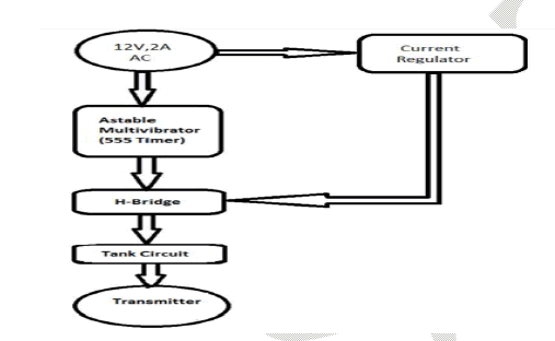
| The tank circuit or LC circuit used here to bring the circuit rest from the oscillation and damping by bringing the circuit in resonance condition. |
| H Bridge is used to force a load to switch in two directions. Astable multivibrator using by the IC 555, and the supply given from single phase to 12V AC Step down transformer. |
 |
b. Coil design |
| We have tested this technique on many designs of coils with that we got better output with the coil having L and C values as 3.66 H and 100nF respectively. When the supply is given to the coil the magnetic field will be produced around the coil and it will be transmitted to the atmosphere. |
IV. RECEIVER SECTION |
 |
a. Reciver description |
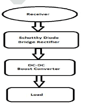
| Rectifiers have many uses, but are often found serving as components of DC power supplies and high-voltage direct current power transmission systems. Rectification may serve in roles other than to generate direct current for use as a source of power. As noted, detectors of radio signals serve as rectifiers. Boost converter is a DC-to-DC power converter with an output voltage greater than its input voltage. It is a class of switched-mode power supply (SMPS) containing at least two semiconductor switches (a diode and a transistor) and at least one energy storage element, a capacitor, inductor, or the two in combination. |
b. Coil design |
| The receiver coil consists of similar tank circuit as that of transmitter coil, its capacity is provided such that 63.3 Hertz and 10 nF. We have designed the receiver coil in order to utilize the maximum flux transmitted by the transmitter. When the receiver is get into the magnetic field according to the faraday’s law of electro-magnetic induction. |
V. PRODUCTIVITY |
a. LED |
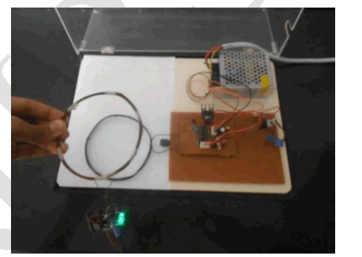
| An LED lamp is a light-emitting diode (LED) product that is assembled into a lamp (or light bulb) for use in lighting fixtures. LED lights come to full brightness without need for a warm-up time. So the wireless power transmission displayed by the LED. |
b. Mobile phone |
| Mobile phones can usually accept a relatively wide range of voltages, as long as it is sufficiently above the phone battery's voltage. However, if the voltage is too high, it can damage the phone. Mostly, the voltage is 5 volts or slightly higher, but it can sometimes vary up to 12 volts when the power source is not loaded. |
 |
VI. CONCLUSIONS |
| With such a wide-ranging application space, we feel that the use of resonance to enhance wireless power transfer will be prevalent in many areas of life in the coming years. Standards Development Organizations (SDOs) are now developing interoperability guidelines for highly-resonant wireless power transfer to ensure that mobile devices from different vendors can charge anywhere in a common wireless ecosystem. As these efforts progress, expect to see wireless power technology deployed in these and many more applications. Though short distance wireless electricity will be implemented in near future but long distance transmission is the dream that can be true one day. Wireless electricity transmission, if successful will definitely change the way we live. Imagine cell phones, laptops, digital camera's getting self charged. At the same time it will be able to come up with the commercial system soon. |