Research & Reviews: Journal of Material Sciences
ISSN:2321-6212
ISSN:2321-6212
1 Hubei Wisdom Comprehensive Energy Industry Technology Research, Wuhan, China
2 Division of Fuel Cell and Battery, Dalian National Laboratory for Clean Energy, Dalian Institute of Chemical Physics, Chinese Academy of Sciences, Dalian, China
3 Wuhan Guide Infrared, Wuhan, China
Received: 29-May-2024, Manuscript No. JOMS-24-137603; Editor assigned: 03-Jun-2024, PreQC No. JOMS-24-137603 (PQ); Reviewed: 17-Jun-2024, QC No. JOMS-24-137603; Revised: 24-Jun-2024, Manuscript No. JOMS-24-137603 (R); Published: 01-Jul-2024, DOI: 10.4172/2321-6212.12.2.003
Citation: Xu S, et al. Layered/Spinel Heterostructured Li-Rich Cathode Materials without Oxygen Loss in Lithium-ion Battery. RRJ Mater Sci. 2024;12:003.
Copyright: © 2024 Xu S, et al. This is an open-access article distributed under the terms of the Creative Commons Attribution License, which permits unrestricted use, distribution, and reproduction in any medium, provided the original author and source are credited.
Visit for more related articles at Research & Reviews: Journal of Material Sciences
Lithium-excess manganese layered oxides, which are commonly described by the chemical formula xLiMnO3·(1-x) LiMO2 (M=Co, Ni, Mn, etc.), are of great importance as cathode materials for rechargeable lithium batteries. A mechanism involving simultaneous Li and O removal is often proposed. Oxygen loss and MnO2 formation appear when first charging across a voltage plateau at 4.5 V vs Li/Li+, which is bottleneck of industrialization for the resulting security problems. In our recent findings, layered/spinel hetero structured Li-rich material Li1.2Ni0.2Mn0.6O2 consist of Li2MnO3, LiNiMnO2 and LiNi0.5Mn1.5O4 without oxygen loss was desired. After assembling it into lithium-ion battery, CV curves have no oxygen evolution peak and no oxygen appears in situ Differential Electrochemical Mass Spectrometry (DEMS). According to the first principle, Li+ ions in Li2MnO3 de-intercalate then Ni2+ ions of LiNi0.5Mn1.5O4 migrate into the sites when first charging, which avoids the oxygen loss from the collapse of Li2MnO3. The exist of spinel phase make the phase transition process of circulation stable, which contributed to the high cycling performance for lithium-ion battery (300 and 220 mAh g-1 after 200th cycles at 0.1 and 0.5C-rate (1C=250 mA g-1).
Li-rich; Cathode materials; Oxygen loss high capacity; Lithium-ion batteries.
As the new energy industry booms, Lithium-Ion Batteries (LIBs) with higher energy and power densities as the leading role of battery industry is applied to 3C, energy storage and many other fields such as Hybrid Electric Vehicles (HEVs) and Electric Vehicles (EVs).
Layered structure Li-rich materials xLi2MnO3 (1−x) LiMO2 (M = Mn, Ni, and Co) (LMR) are more and more attractive to researchers because of its high theoretical specific capacity (350 mAh g-1) and high discharge voltage (4.5 V).
However, the materials also suffer from some disadvantages with initially large capacity loss and poor rate cycling performance [1-7]. As reporters’ views, oxygen loss is the main reason for its poor stability [8, 9]. It is generally believed that the charging process of the materials is divided into two stages. When the charge voltage vs Li/Li+ below to 4.5 V, the capacity is mainly provided by LiMO2 component. After charged to 4.5 V, there is a long plateau accompanied with a net loss of Li2O from the Li2MnO3 component [10]. The net loss of Li2O leads to a huge irreversible capacity loss in the initial cycle [10,11]. Meanwhile, some oxygen extracted from the lattice results in the transition metal ions migration leading to phase transformation to spinel structure [10,12-17]. The cyclic stability of the material is reduced rapidly due to the structural failure, which is the main factor in its inability to enter the market.
Layered/Spinel Hetero-structured (LSH) Li-rich materials is a new type of material that relieves voltage attenuation of LMR proposed by Su etc. [18] for the first time in 2013, which was improved successively by researchers in recent years [19-29]. Spinel structure was brought in to lower the initially irreversible capacity and maintain the phase transition stable. Spinel coating is preferred by researchers attributed to the consistency with phase transition [30-37]. So far, the coating methods include from simple sol-gel, co-precipitation to complicated as Atomic Layer Deposition (ALD), Thermal Evaporation (TE) Pulsed Laser Deposition (PLD) and reactive magnetron sputtering (RMS) [37-49]. These methods are all adding a coating process after preparing LMR, some of them are difficult to industrialize. What’s more, it did not fundamentally solve the problem of oxygen loss.
This study presents a concept to obtain LSH without oxygen loss. Firstly, hydrothermal method was used to obtain the uniform-sized microspheres of Ni0.2Mn0.6CO3. With annealing at the appropriate temperature, spinel structure material LiNi0.5Mn1.5O4 was formed with LiMO2. It is worth mentioning that the nickel ions in spinel phase play a fatal role in the process without oxygen loss. In the process of charging, lithium ions of Li-Mn layer off from Li2MnO3, nickel ions from spinel phase move into the above lithium vacancy, directly transformed Li2MnO3 into LiMO2, which not only has no collapse of Li2MnO3 structure and oxygen loss, but also enhance the capacity attributed to the high theoretical specific capacity of LiMO2. In order to explain the reaction mechanism of the material and its corresponding changes of crystal structure, composition and electrochemical process more specifically, various properties involving morphological, structural, and electrochemical performances of as-prepared material Li1.2Ni0.2Mn0.6O2 (LNMO) were evaluated and probed. The first principle was applied to the diffusion process of ions during charging.
Experimental details
NiCO3 and CoCO3 were mixed and ground at a ratio of 1:3, urea is used to regulate the pH value for hydrothermal reaction at 200°C for 24 hrs with ethanol as the solvent. Ni0.2Co0.6CO3 was obtained after dehydration at 120°C, Ni0.2Co0.6O2 was obtained after annealing at 450°C for 5 hrs. Li2CO3 and Ni0.2Co0.6O2 were mixed and ground at a ratio of 3:5, Li1.2Ni0.2Co0.6O2 was obtained after annealing at 850°C for 12 hrs.
The structure and crystallinity of the samples were characterized using an X-ray diffractometer (XRD; Rigaku X-ray diffractometer) with Cu Kα radiation source (λ=0.1506 nm) under a voltage of 40 kV and a current of 30 mA. The morphology and elementary composition of the samples were observed by scanning electron microscopy (SEM; JEOL JSM, 65 10 V), transmission electron microscopy (TEM; JEM-2100, 200kV) and Energy-Dispersive Spectrometer (EDS). The chemical states of LNMO during the circulation were analyzed by X-ray photoelectron spectroscopy (XPS; Thermofisher ESCALAB 250Xi, 15kV, 10.8mA). Here, we demonstrate directly that there is no oxygen produced during charging to 4.8 V, by in situ differential electrochemical mass spectrometry (DEMS; HIDEN HPR20, 70 eV, 900 V).
A mixture of 80% wt Li1.2Ni0.2Mn0.6O2, 10% wt. super p, and 10% wt. Polyvinylidene Fluoride (PVDF) dissolved in 1-methyl-2-pyrrolidone (NMP) was stirred to form a homogeneous slurry. The slurry was spread on an Al foil coated carbon to form an electrode sheet. The sheet was dried at 120°C for 10 hrs in vacuum oven. Half-cells were assembled in an Ar-filled glove-box with 1 mol/L LiPF6/EC+DMC (1:1 in volume) as the electrolyte and metallic lithium foil as the counter electrode.
The Cyclic Voltammetry (CV) was measured by an electrochemical workstation (CHl60E) between 2 and 4.8 V at a scan rate of 0.3 mV s-1. The Electrochemical Impedance Spectroscopy (EIS) measurements were performed with CHl760E over the frequency range of 0.01~100 kHz with an amplitude of 3 mV. Galvanostatic charge/discharge cycling for lithium-ion batteries was carried out in the range of 2.0~4.8 V at 0.1 and 0.5 C-rate (1C= 250 mA g-1). The densities used for rate capability for lithium-ion batteries were from 0.1 to 10 C, and for solid-state lithium batteries were from 25 mA g-1 to 2500 mA g-1.
Material characterization
The synthesis of LNMO was achieved by a two-step procedure divided into hydrothermal and annealing methods shown in Scheme 1. Figure 2 (a, b) are the X-ray diffraction patterns of the precursor Ni0.2Mn0.6CO3, Ni0.2Mn0.6O2 and product Li1.2Ni0.2Mn0.6O2. The precursor before annealing is Ni0.2Mn0.6CO3, whose diffraction peaks is consisting with MnCO3 (a=b=4.790 Å, c=15.694 Å, space group R-3c (167), JCPDS NO.14-1472). The precursor after annealing is consist of NiMnO3 (a=b=4.890 Å, c=13.580 Å, space group R-3 (148), JCPDS NO.48-1330) and Mn2O3 (a=9.416 Å, b=9.424 Å, c=9.405 Å, space group Pcab (61), JCPDS NO.24-0508). The characteristic diffraction peaks of layered Li-rich materials can be observed clearly in Figure 2b and are well indexed to the α-NaFeO2 layered structure with R -3 m symmetry except for weak superlattice reflections around 20-25° corresponding to a Li2MnO3 component with monoclinic structure (space group C/2m). More importantly, it presents the characteristic diffraction peaks at 36° and 38° respectively represent the lattice plane (311) and (222) of spinel structure LiNi0.5Mn1.5O4. Know then, the sample is composed of three phases LiMO2, Li2MnO3 and LiNi0.5Mn1.5O4 accurately. SEM images of precursor Ni0.2Mn0.6CO3, Ni0.2Mn0.6O2 and product Li1.2Ni0.2Mn0.6O2 are present in Figure 2c. The diagram shows the Ni0.2 Mn0.6CO3 obtained by hydrothermal method as microspheres, and core-shell structure forms after early sintering due to the loss of CO2. The product restores the microsphere, from whose elemental mapping the distribution of elements of Ni, Mn and O is even, and there is no obvious difference of phase.

Figure 1: Schematic illustration on the formation process of rich-LI LNMO

Figure 2: (a, b) XRD of precursor Ni0.2Mn0.6CO3, Ni0.2Mn0.6O2 and product Li1.2Ni0.2Mn0.6O2; (c) SEM images of above materials. 
The phase transition in the circulation
The most important result of this work shows in Figure 3a. LNMO was assembled into the cell as the cathode material and tested in-situ DEMS. From the open circuit voltage 3.1 V to the charging voltage 4.8 V, there is no oxygen produced at all, which is an essential difference from the traditional LMR [11]. Furthermore, the oxygen precipitation peaks of 4.5 V disappear in Figure 3a and 2c, different from all the CV curves of traditional LMR. This means that the traditional phase transition mechanism has changed in this material LNMO. The structure of the material has changed dramatically too in Figure 3b. As the circulation progresses, it can be seen that the Li2MnO3 phase with the characteristic diffraction peak at about 21°is gradually disappearing and the spinel phase LiMn2O4 appears gradually, which indicates that Ni ions in LiNi0.5Mn1.5O4 move off. The corresponding situation occurs in Figure 3d, the voltage plateau represented for the oxidation of Ni ions at 4.73 V is gradually getting shorter, which is completely disappear after around 10 cycles. Compared the REDOX peak of Figure 3c with the voltage platform of Figure 3d, the platform of layered compound LiMO2 is becoming more and more obvious in the circulation of real cell. This also corresponds to the phenomenon that the discharge capacity is higher and higher because the theoretical specific capacity (237 mAh g-1) of layer compounds is higher than that of the spinel phase (140 mAh g-1).

Figure 3: (a) In-situ DEMS of LNMO cell between 3.1 to 4.8 V at the scanning speed of 0.5 mV s-1. (b) Ex-situ XRD of
LNMO in the circulation. (c) CV curves of LNMO between 2-4.8 V at the scanning speed of 0.3 mV s-1. (d) the typical
charge and discharge curves of LNMO. 

The above conclusions are further confirmed in Figure 3, which shows the HRTEM, SAED and EDS analysis of LNMO before and after 5 cycles. In the initial state, the material consists of three phases shown in SAED, lattice plane for LiMO2, lattice plane for Li2MnO3 and lattice plane for LiNi0.5Mn1.5O4. EDS analysis corresponding to LiNi0.5Mn1.5O4 shows the auto ratio O: Mn: Ni is 12.85: 3.12: 0.9, which is similar to the theoretical ratio 4:1.5:0.5. While after 5 cycles, LiNi0.5Mn1.5O4 and LiMO2 still exist except for Li2MnO3. And in contrast to the XRD result, LiMn2O4 also appears. There is a layer of amorphous phase on the edge of the crystalline phase, which is considered as the SEI film.
From the above phenomena, we can conclude that the Li2MnO3 is lost in the circulation, and Ni ions are gradually migrating out of spinel phase LiNi0.5Mn1.5O4. The results of XPS give some clues to the transformation of LNMO. Ni-Mn bond intension in LiNi0.5Mn1.5O4 is getting weaken in Figure 4b, which means Ni-Mn bonds are getting fewer and fewer due to migration of Ni ions. From Figure 2c, the binding energy around 73 eV represent for MnO obviously enhance, which can be due to the reduction of Mn3+ in spinel phase LiMn2O4. The binding energy around 54.5 eV indicates Li+ ions mainly exist in the Li-Mn layer of Li2MnO3 at the initial state, Li+ ions in layered structure proportion increase after 5 cycles shown in Figure 4d, in which the binding energy was transferred to 55.5 eV. The result of the chemical state of oxygen confirms it. The binding energy of oxygen at 528.5 eV denotes that oxygen is in the tetrahedron, while in the octahedron at 531.5 eV. The oxygen is more in the tetrahedron of the spinel phase LiNi0.5Mn1.5O4 and more in the octahedron of the layered structure LiMO2 after 5 cycles shown in Figure 4e. In combination with the change of chemical state of all elements, we have reason to believe that the Ni ions are migrating and the layered phase LiMO2 increases in the circulation process.

Figure 4: The HRTEM, SAED and EDS analysis of LNMO before and after 5 cycles.
The electrochemical properties of Li1.2Ni0.2Mn0.6O2 for LIBs
Attributed to the change of lithium de-intercalation mechanism in the first cycle, LNMO did not lose oxygen, and the structure remained relatively stable for a long time. Therefore, the electrochemical performance of LNMO is stable and excellent. The cycling and rate performance of LNMO are shown in Figure 5 (a, b). The capacity of LNMO maintain 300 mAh/g at the rate of 0.1 C (25 mA g-1) and 200 mAh g-1 at the rate of 0.5 C after 200 cycles. In the process of the initial cycles, the capacity shows an uptrend, which is the influence of transformation from Li2MnO3 to LiMO2.

Figure 5: The XPS analysis of LNMO for (a) NI2P, (b) Ni LM2-MN2P, (c) MN3S, (d) Li1s, e O1s before and after 5 cycles.
After several cycles, the phase transition is completed. And the structure is relatively stable composed of layered LiMO2 and spinel LiMn2O4 with no attenuation of the voltage platform and no decay of capacity. Figure 5b reveals good rate performance, from which the capacity of LNMO are 250, 220, 200, 150, 100, 50 mAh g-1 at the rate of 0.1, 0.2, 0.5, 1, 5,10 C, respectively. When the rate returns to 0.1 C, the capacity goes back to 250 mAh g-1.
The Nyquist plots for LNMO derived from the EIS measurements without circulation and after 5th, 20th cycles are shown in Figure 5c. All the spectra exhibit a semicircle at high-medium frequencies corresponding to the charge transfer resistance (Rct). Note that rather different behavior in Rct is observed. As shown here, Rct increases from 86.4 to 200.5, 259.8 Ω, which means the surface electrode reaction is increasingly difficult as the circulation goes on. Inclined line in the low-frequency range is considered as the Warburg impedance, corresponding to the Li+ diffusion inside the electrode material [32]. The numerical value of the Li+ diffusion coefficient in the electrode can be estimated from the following equation [32].
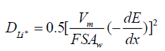
Figure 5d shows the trend that the slope represents Warburg coefficients (Aw) increases with circulation, which is belong to the change of crystal structure. The Warburg coefficients (Aw) of the cells with circulation and after 5,20 cycles are 1454.9, 2040.3, 2375.9 Ω/ω-1/2, respectively. These results are consistent with the above electrochemical properties of LNMO.

Figure 6: (a) The cycle performance of LNMO at the rate of 0.1C and 0.5C (b) The rate performance of LNMO (c) Electrochemical impedance spectra (EIS) of LNMO. (d) Linear fitting of Warburg impedance of LNMO. Note: 

In this work, the lithium-rich manganese-based cathode material LNMO was synthesized by hydrothermal-annealing method. X-ray diffraction measurements shows the synthesized LNMO was composed of LiMO2 and Li2MnO3 with layered structure and LiNi0.5Mn1.5O4 with spinel structure. In the initial cycling process of general lithium-rich manganese-based materials, due to the irreversible transformation of the layered structure of Li2MnO3 into MnO2, Li+ and oxygen, a large amount of oxygen will escape, which will cause side reactions to lead to the deterioration of the electrolyte and the serious attenuation of battery capacity. CV curves of the as-prepared LNMO have no oxygen evolution peak and no oxygen appears in situ Differential Electrochemical Mass Spectrometry (DEMS) [50]. According to the first principle, Li+ ions in Li2MnO3 de-intercalate then Ni2+ ions of LiNi0.5Mn1.5O4 migrate into the sites when first charging, which avoids the oxygen loss from the collapse of Li2MnO3. The exist of spinel phase make the phase transition process of circulation stable, which contributed to the high cycling performance for lithium-ion battery (300 and 220 mAh g-1 after 200th cycles at 0.1 and 0.5C-rate (1C= 250 mA g-1).
The authors acknowledge financial support from the Key Program of the Chinese Academy of Sciences (Grant No. KGZD-EW-T08).
[Crossref] [Google Scholar] [Pubmed]
[Crossref] [Google Scholar] [Pubmed]
[Crossref] [Google Scholar] [Pubmed]
[Crossref] [Google Scholar] [Pubmed]
[Crossref] [Google Scholar] [Pubmed]
[Crossref] [Google Scholar] [Pubmed]
[Crossref] [Google Scholar] [Pubmed]
[Crossref] [Google Scholar] [Pubmed]
[Crossref] [Google Scholar] [Pubmed]
[Crossref] [Google Scholar] [Pubmed]
[Crossref] [Google Scholar] [Pubmed]
[Crossref] [Google Scholar] [Pubmed]
[Crossref] [Google Scholar] [Pubmed]
[Crossref] [Google Scholar] [Pubmed]
[Crossref] [Google Scholar] [Pubmed]
[Crossref] [Google Scholar] [Pubmed]
[Crossref] [Google Scholar] [Pubmed]
[Crossref] [Google Scholar] [Pubmed]
[Crossref] [Google Scholar] [Pubmed]
[Crossref] [Google Scholar] [Pubmed]
[Crossref] [Google Scholar] [Pubmed]
[Crossref] [Google Scholar] [Pubmed]
[Crossref] [Google Scholar] [Pubmed]
[Crossref] [Google Scholar] [Pubmed]
[Crossref] [Google Scholar] [Pubmed]
[Crossref] [Google Scholar] [Pubmed]
[Crossref] [Google Scholar] [Pubmed]